The latest versions of the above toolkits have been adopted.
Drawing Enhancements
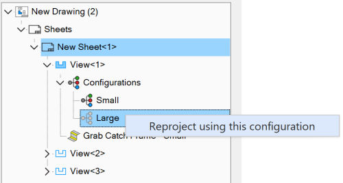
Change a Drawing View's Active Configuration
The actively displayed configuration of a drawing can now be changed from the Drawing Explorer.
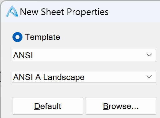
Drawing Template Selection
Templates are now categorized by standard which is remembered. Only templates adhering the standards you typically use are shown by default.
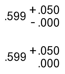
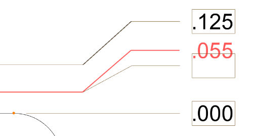
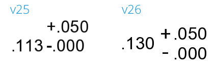
0-value Tolerances
An option now exists to remove the + or - symbols for tolerance values of 0.
Smart Dimensions
Smart dimensions are now much better are determining whether a dimension will fit "Inside" without dimension line overlap. This results in dimension placement that requires much less potential rework after placement.
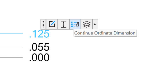
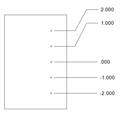
Ordinate Dimensions: Continue Chain
A Continue Ordinate Dimension button has been added to the popup menu on ordinate dimensions to make adding additional elements easy to find.
Ordinate Dimensions: Reposition While Creating
You can now move individual ordinate dimensions left and right while in the ordinate dimension tool, allowing you to reposition dimensions without having to exit the tool.
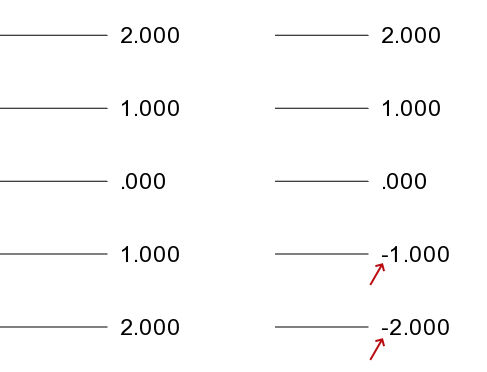
Ordinate Dimensions: Negative Values
A new option under Dimension Styles allows you to show negative signs on dimensions to the left or to the right of the 0 dimension, e.g. -34.2 mm. You can also flip which side of the zero dimension is considered negative. The Dimension Style applied to the base (0) dimension controls these features.
Ordinate Dimension: Independent Repositioning
Right-clicking on an ordinate dimension allows you to unselect the Align Ordinate Dimension option. This allows you to independently reposition the ordinate dimension's offset from the chain.
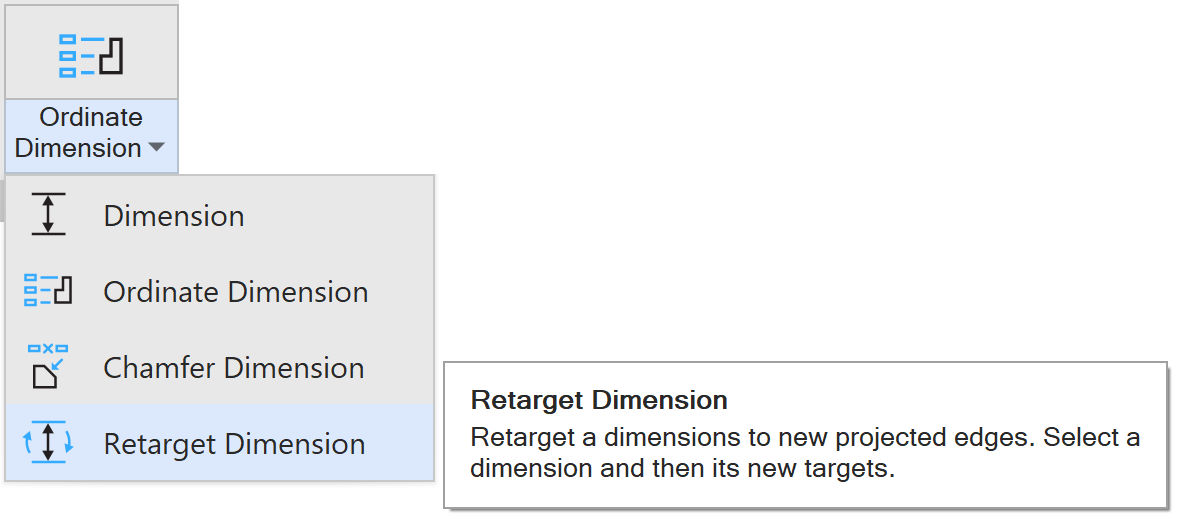
Retarget Dimension Tool (Drawings Only)
A new tool allows you to redefine the target geometry associated with a dimension while maintaining customizations to the dimension. No more "delete and remake". Also works to quickly reassociate disassociated dimensions should they occur, while keeping rework to a minimum.
Select and Delete Dimensions within Dimension Tool
It is now possible to select a single or multiple dimensions and press Delete while in the Dimension tool to remove dimensions. Previously it was only possible to delete one at a time via the right-click menu or to exit Sketch Mode and multi-select them with the Select tool.
Set Multiple Dimension Properties within Dimension Tool
You can now multi-select dimensions while the Dimension tool is active and apply properties to multiple dimensions at once, without having to first exit Sketch Mode and then use the Select tool.
Arrow-Based Dimension Alignment
Arrows now snap to each other when dragging dimensions, making perfect arrow alignment easy.
Choice of Decimal Separator ( 1.250 vs 1,250 )
Previously the separator used in drawings was inherited from the regional settings of the machine. Most of the time this is ok, but a new option exists to choose whether a comma or period is used as a separator in the File Properties > Display of drawing files.
ISO 8601 Date Format Option
Previously the date format was inherited from the machine's system settings. This could make correctly formatting to ISO 8601 difficult. A new setting in File Properties > Display of drawing files allows ISO 8601 to be explicitly chosen.
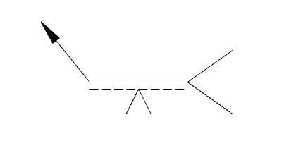
ISO Weld Symbols
ISO Weld symbols now have an option to show a dashed line such that the standard can be adhered to. For technical reasons this can only be applied to new Weld symbols created in v26 or later.
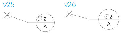
Dimension and Annotation Appearance
Various enhancements have been made across dimensions and annotations to improve their appearance and internal alignment. Some examples:
DIN Templates
Added several DIN drawing templates.
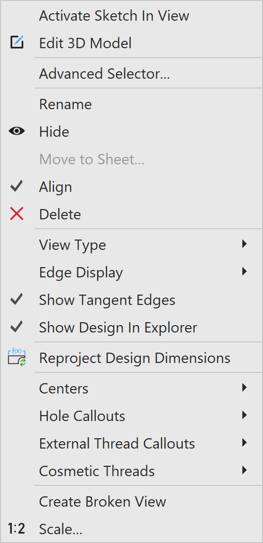
View-Based Right-Click Menu
Restructured this menu and added in several tools.
Drawing Bugfixes
Dragging Feature Control Frames
Dragging Feature Control Frame annotation in 2D drawings multiple times can cause a crash.
Comma-separated Dimensions
Comma separator in a dimension would sometimes revert to decimal-separation when a saved drawing was reopened,
Cursor Issue
The cursor when in the Ordinate Dimension tool would show the wrong image after zooming in some cases.
Dimensioning on Pre-Selected Views
Cannot drag existing dimensions while creating new ones if dimension command is launched with a view pre-selected.
Continuing Ordinate Dimensions
In some cases, you could incorrectly continue ordinate dimensions by selecting figures on views other than the one that contain the base dimension.
Save All As in a Drawing with Projected Design Dimensions
During a Save All As operation on a drawing that contains projected Design Dimensions (not regular dimensions), if the file names are updated the projected design dimensions become corrupted.
Insert Custom Symbol in Empty Drawings
If a drawing was empty, the Insert Custom Symbol tool was not available from the Custom Symbol Dropdown, which was itself grayed out.
BOM Callout Arrowhead Not Solid
In some cases, BOM Callout arrows were not filled solid.
Ordinate Dimensions with Tolerances Overlap Dimension Lines
In some orientations, ordinate dimensions with tolerances would overlap the dimension lines. Additional padding has been added.
Horizontal Dimension Padding
Many dimensions had padding logic that resulted in incorrect extra space between the left-most character and the dimension line, causing the dimension text to be un-centered within the dimension space.
Angular Dimension Spacing between ° and Number
There was extra space between the number and the ° symbol causing dimensions to look like 45 ° instead of 45° . This applies to drawings and modeling environments.
Realtime Line Weights in Scaled Views Caused Thickness Issues
Several fixes have been made related to dimensions, centerlines, cosmetic threads, etc. in scaled views such that they show correct thicknesses.
Counterbore Hole Cosmetic Threads
Drawing Cosmetic Threads for Counter-Holes terminate Incorrectly If the Hole operation's Reverse option is checked.
Dimensions to Center Marks
Dimensioning to Center Marks could result in odd behavior or require multiple steps to expose the desired node. This behavior has been improved to "just work" much more often.
Chamfer Dimension Target Selection
Chamfer Dimension tool incorrectly allowed selection of targets from inactive drawing views.
User-Created Layers Disappear
User created layers disappear from drawing after user edits Sheet Properties without changing drawing template.
Incorrect Layer Transfer
Drawing Template figures sometimes incorrectly acquire layer properties of a newly added layer in 2D drawing.
Dash Patterned Lines
Figures having a dash patterned line style show up as solid lines immediately after opening a drawing.
Incorrect 2D Point Visualization
2D drawing point (cross) displays as large dot when opening saved drawing.
Realtime Line Widths for Template Lines
Drawing template line widths were not displaying or printing correctly in some cases with realtime line widths turned on.
Realtime Line Widths for Exploded Trails
Exploded view trails (in drawings) display with the incorrect line width when realtime line widths is turned on.
Realtime Line Widths for BOM Tables
BOM Table grid lines display with the incorrect line width when realtime line widths is turned on.
Realtime Line Widths for Multi-Model-Unit Views
Precise drawing views with parts of different model units get incorrect line widths with realtime line widths turned on.
Realtime Line Widths for Sketch Figures
Sketch figures in drawing sheet containing no views get incorrect line widths with realtime line widths turned on.
UI
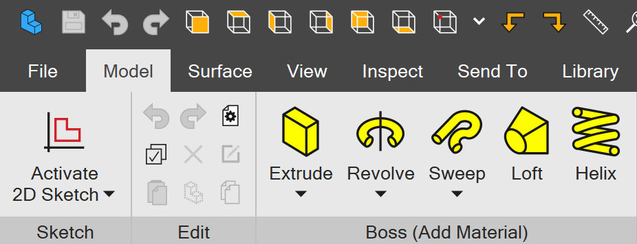
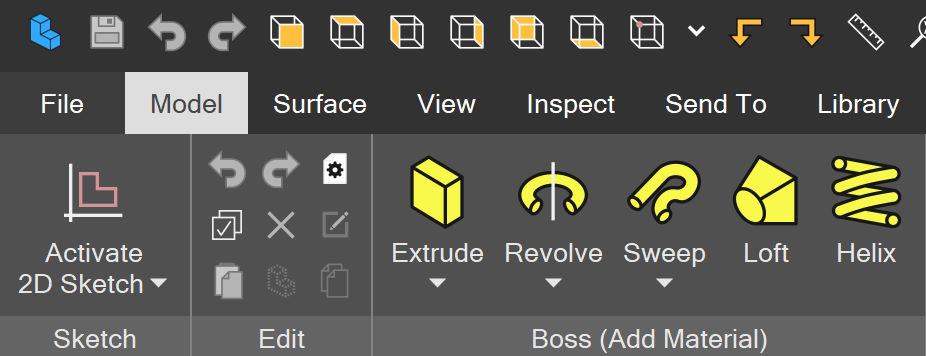
All Ribbon, Toolbar, Menu, Popup, and Explorer Icons Now Vector-Based
All icons have been redone to be vector-based meaning they are crisp at any resolution. This change does not affect most dialogs (yet). This change is the first of a series of large user interface changes that will occur over the next few releases.
Dark Mode, Color Blind Modes
New color schemes for Dark Mode and various Colorblind-friendly palettes have been added. Note that these changes currently only affect the Ribbon, Toolbars, Menus, and all of their icons. Eventually, these changes will affect the entire product including the various Explorers and all dialogs.
Ambient Occlusion Global Disable Option
Ambient Occlusion is on by default for legacy parts saved before Ambient Occlusion was implemented. For those wishing to completely disable it, a new System Option exists to disable it for all parts and assemblies.
Ambient Occlusion Disabled in Sketch Mode
Ambient Occlusion is now temporarily disabled in Sketch Mode automatically. This prevents visual artifacts related to the grid and other distractions.
Feature-Based Edge Color Deprecation
Feature Color's Edge Color setting is being deprecated. It is now grayed out and will be removed in a subsequent release.
Default Circular Pattern Type
The default circular pattern type is now Equal Angle, so items are spaced equally around a center point. The dialog will also remember what you used last.
Sketch Inference Line Visibility
Sketch inference lines are now larger and more clearly visible over the grid and/or 3D geometry behind the sketch.
Ordinate Dimension Cursor
Ordinate Dimension now has its own cursor.
Dialog / UI Bugfixes
String Changes
Various string changes across the UI to increase clarity or conciseness.
Right Click Menus in Drawings
Reorganized some menus and added missing tools in some cases.
Custom Symbol missing from Toolbar Customization
Insert custom symbol button was missing in the Customize Toolbar dialog in 2D Drawing.
Script Disabled on Locked Parts
Previously Script's menu was not disabled on locked parts when it should have been.
Selected Reference Figure Tool Not Always Shown in Ribbon
Sometimes selecting a reference figure in sketch mode would not make the tool visibly active in the ribbon.
Standard View Creation Dialog
On some displays it was difficult to see which views were selected and which view type was selected.
Gear/Pulley Input Strings
Changed some verbiage to make the expected inputs clearer.
Assembly Bugfixes
Constraints with Toroidal Geometry
In some cases, constraining toroidal geometry would result in an error message.
Tangent with Offset Constraint Between Part Copies with Model Units Different than the Assembly's Model Units
In these cases, typically on imported parts with model units other than centimeters, the tangent offset would fail.
Part Bugfixes
Design Explorer Drag Operation
An issue was fixed that made sketches disappear temporarily from the Design Explorer in certain circumstances when dragged around the Dogbone.
3D Preview Caused Cancelled Hole Operation to Incorrectly Move Dogbone.
When 3D Preview is enabled, invoking and then cancelling the Hole tool would incorrectly move the Dogbone up one feature, causing the suppression of the feature.
Sketch-Based Design Points on the Sketch Origin
Any Design Points (i.e. Reference Points) created using the 2D sketch origin node lose their reference when the part is reopened.
3D Preview Caused Cancelled Hole Operation to Incorrectly Move Dogbone.
When 3D Preview is enabled, invoking and then cancelling the Hole tool would incorrectly move the Dogbone up one feature, causing the suppression of the feature.
Sketch Status Incorrectly Shows Fully Defined
Within a sketch, the status bar at the bottom would say "Fully Defined" when it should say "Under-defined" in some workflows.
Visibility of Tracing Images
Tracing images that were coplanar with 3D geometry would "fight" for visibility priority with the 3D geometry. This sometimes meant the image would be occluded with geometry. Now Tracing Images have visibility priority with coplanar geometry.
Sheet Metal Bug Fixes
Renaming a Child Flange
Renaming a child flange of a multi-flange operation would not be maintained once regenerated.
Miscellaneous Bug Fixes
Scientific Notation Display Crash
Display of values in scientific notation with a mantissa of 1 can trigger a crash.
Measurement Tool with Threaded Holes
Holes with threads could not be used as inputs to the Measurement tool.
Save Notification
When Save Type was set to Notify, it would sometimes not notify the user if the only change was to part data / properties.
Alibre Script: Polygon
AddPolygon API places polygon at incorrect location.