3D models are the source of truth - if they change the drawings update too.
Comprehensive Detailing
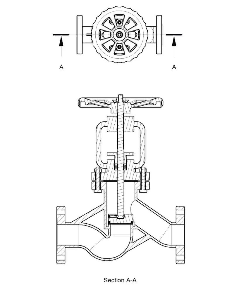
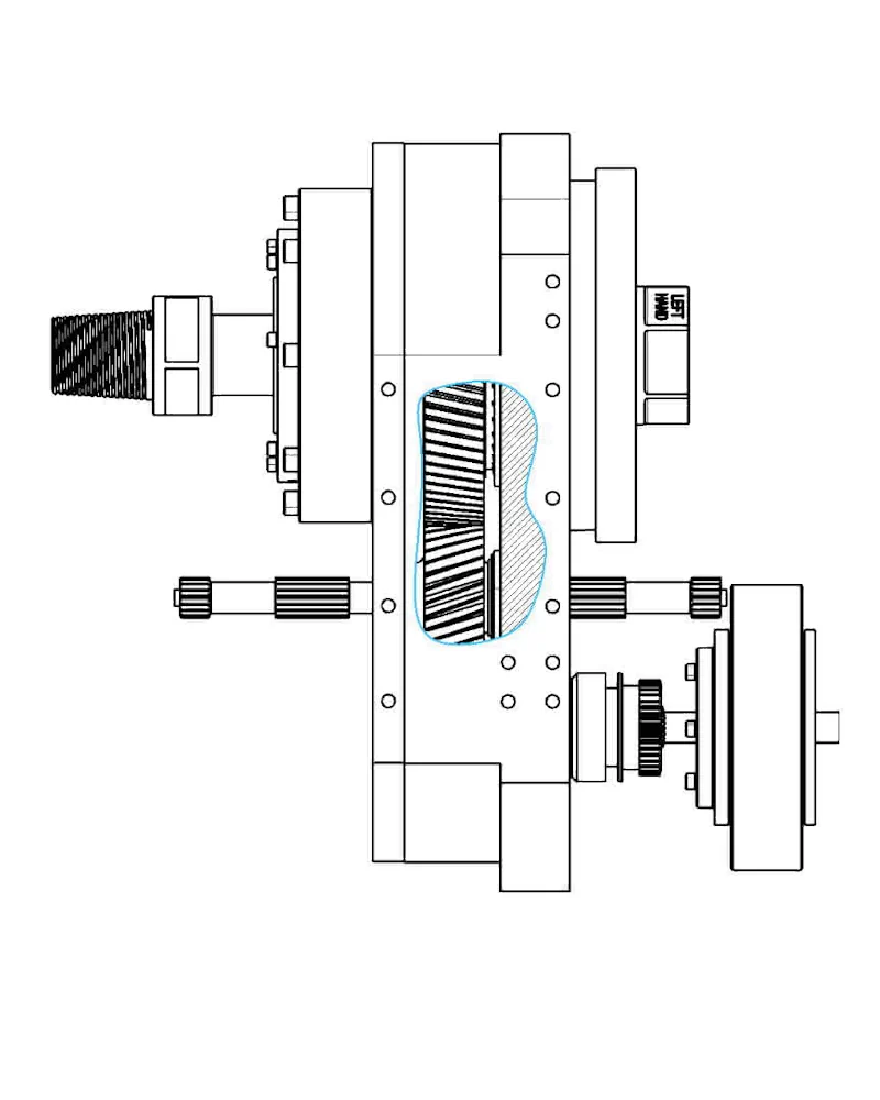
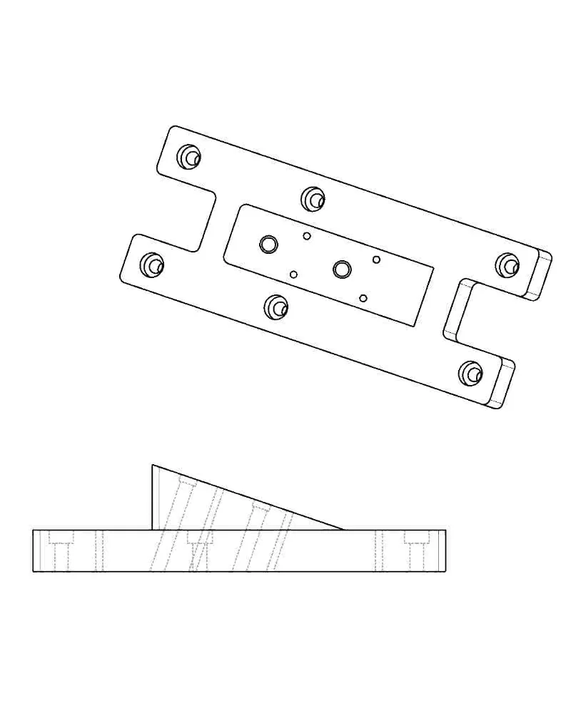
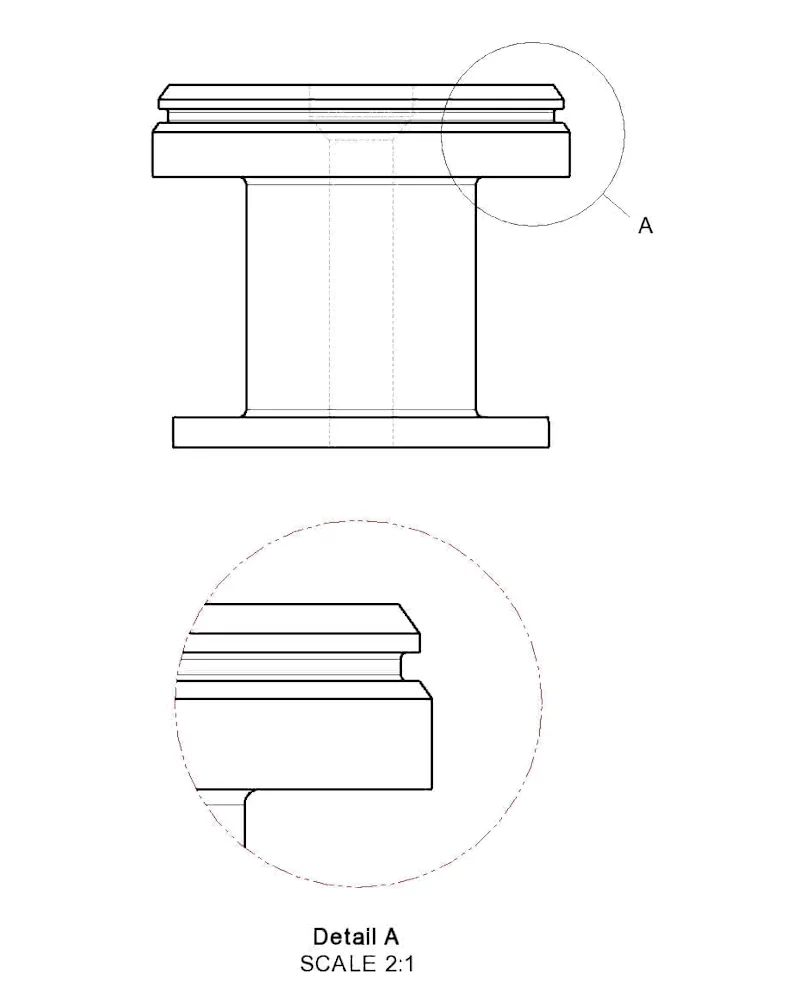
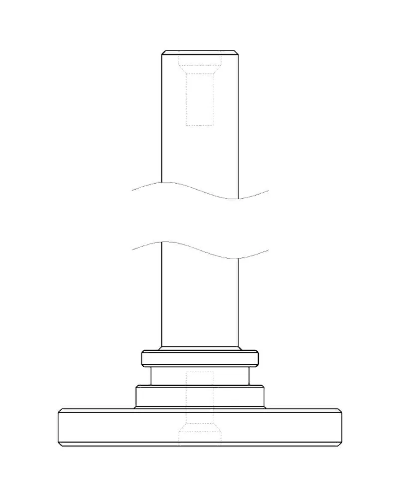
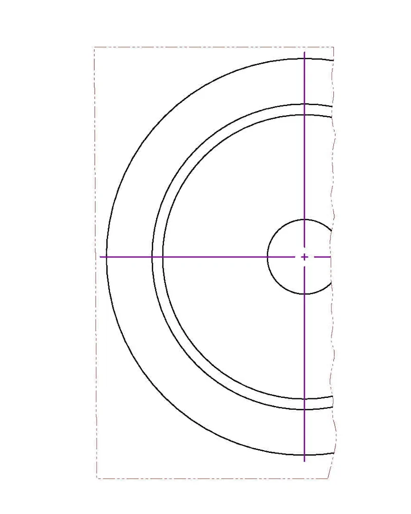
Confidently create any kind of detailing or views that may be required.
Standards Adherence
Create templates with company standards and apply them to drawings.
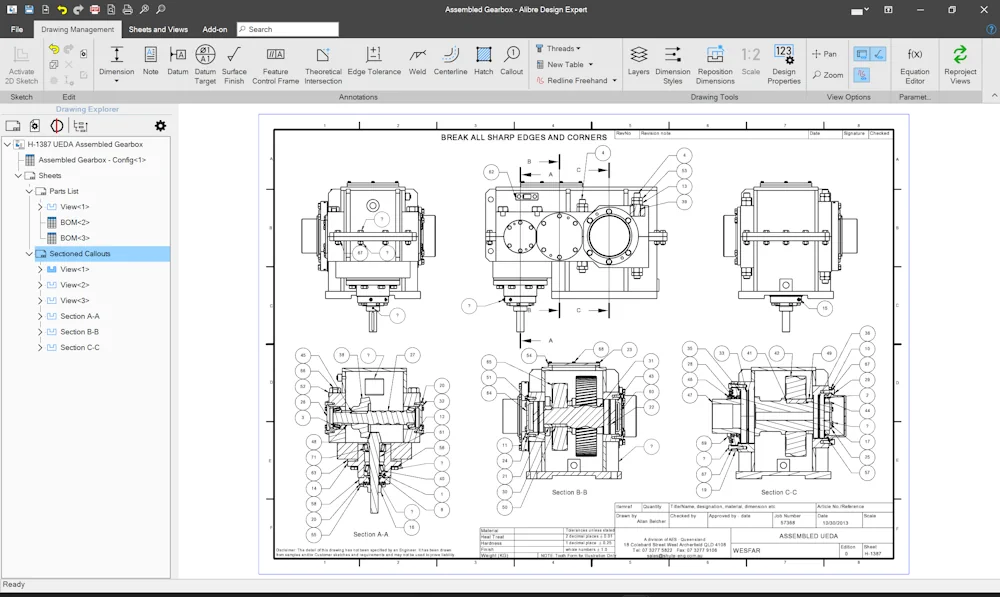
Keeping Drawings Updated
Drawings detect when changes have occurred and update themselves to ensure they reflect the current state of the model and its data, including all:
Model geometry
Dimensions
All drawing views
Bill of materials
Flat patterns
Metadata
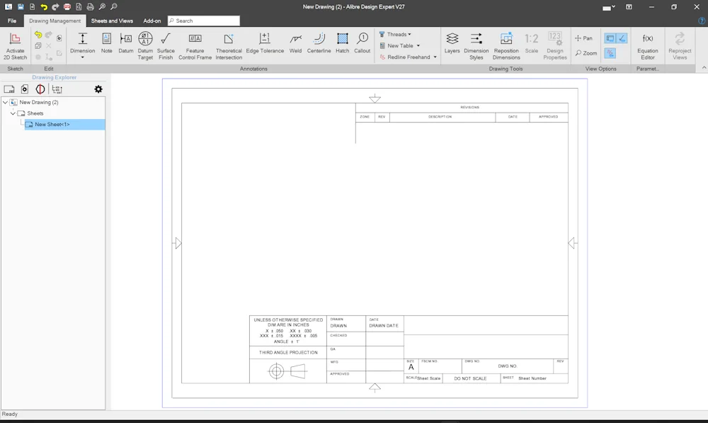
Templating System
Use pre-built templates or create your own to adhere to your company standards. Control the sheet layout, dimension styles, default precision, appearance, and more to minimize tedious detailing tasks and reduce human error.
Project dynamic data into a template - any available design metadata or custom metadata - and it automatically populates the drawing too.
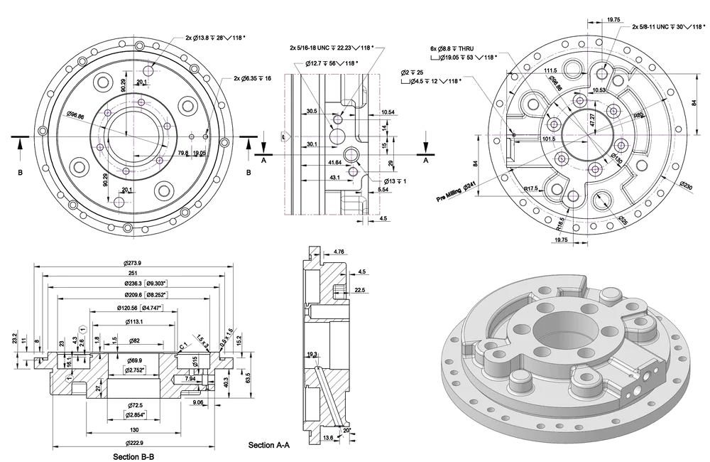
Comprehensive Detailing Suite
An arsenal of tools is available to communicate everything you need to about a model's requirements, including:
Dimensions
Note
Datum
Datum Target
Surface Finish
Feature Control Frame
Threads
Bill of Materials
Theoretical Intersection
Edge Tolerance
Weld
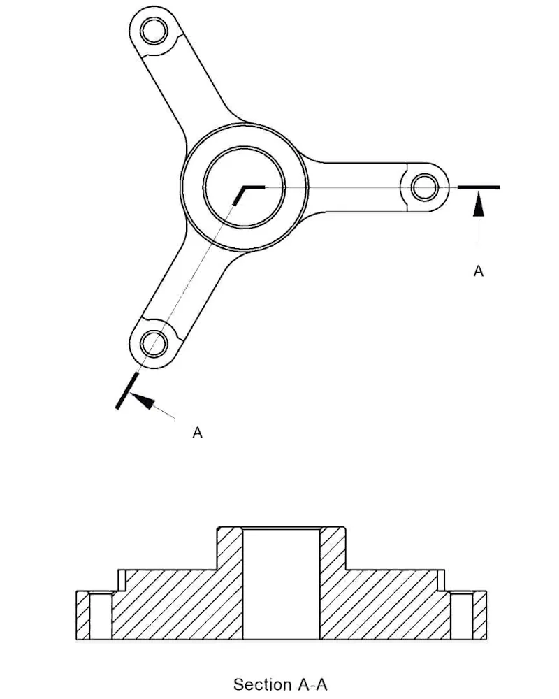
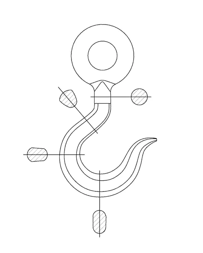
Centerline
Hole & Thread Callouts
Hatch
Callout Ballons
Tables
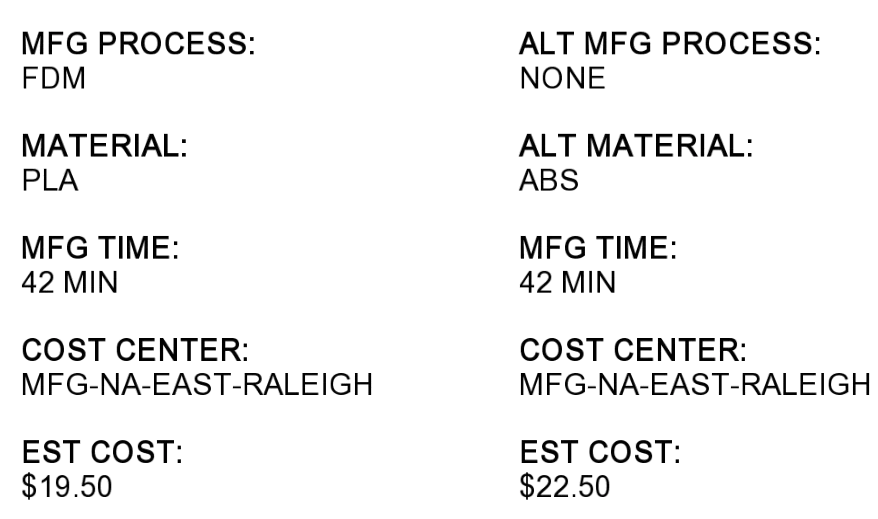
Using Metadata
Use default metadata or create your own custom metadata in 3D models. Then create templates that contain fields for the metadata. When you create a drawing, the fields are populated automatically, and they update if the data changes in the 3D model.
Metadata can be used anywhere on a drawing, including title blocks.
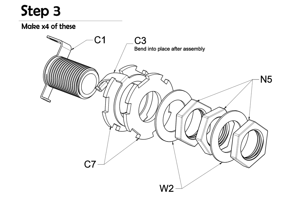
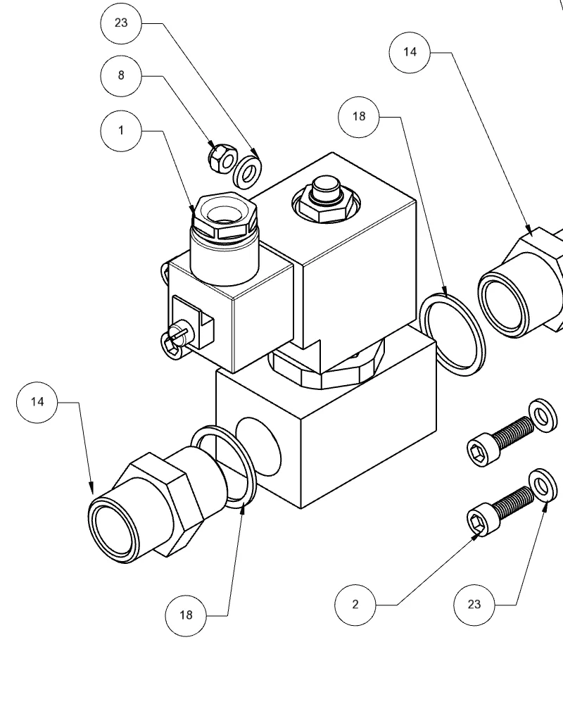
Create End-User Instructions
With exploded views, notes, and callouts, you can create multi-page manuals suitable for step-by-step assembly, servicing, or manufacturing instructions.
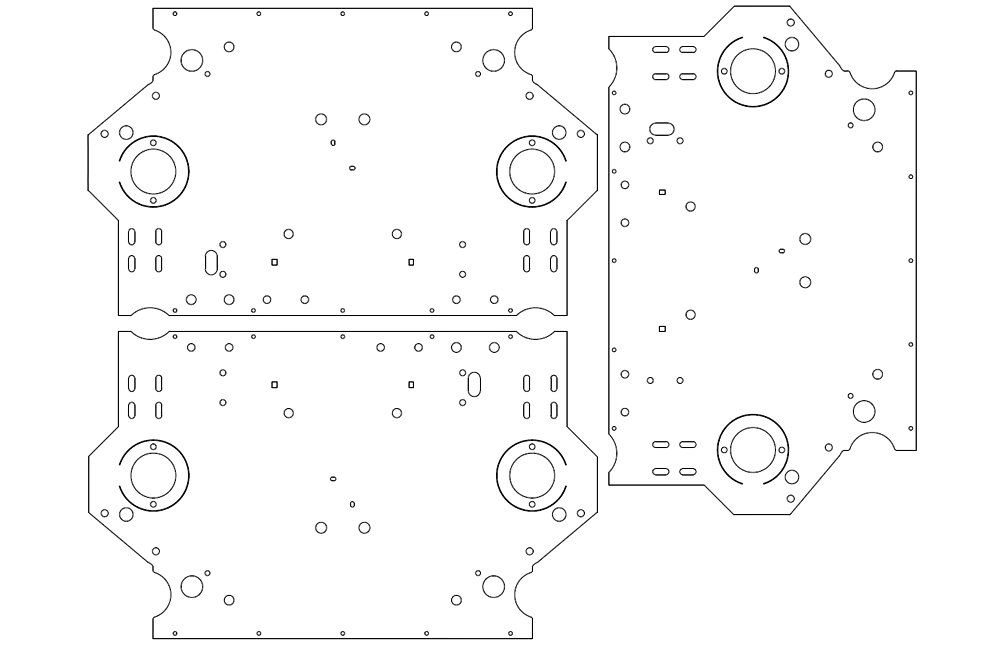
Output Profiles for Machining
Output clean profiles into other systems for CNC, laser/plasma cutting, engraving - any profile-driven process.