Create dynamic and precise representations of your entire product - a virtual twin
Parametric Modeling
Create dynamic and precise representations of your entire product - a virtual twin
Parametric Modeling
Create dynamic and precise representations of your entire product - a virtual twin
Parametric Modeling
Create dynamic and precise representations of your entire product - a virtual twin
Parametric Modeling
Create dynamic and precise representations of your entire product - a virtual twin
Parametric Modeling
Create dynamic and precise representations of your entire product - a virtual twin
Parametric Modeling
Create dynamic and precise representations of your entire product - a virtual twin
Parametric Modeling
Create dynamic and precise representations of your entire product - a virtual twin
Parametric Modeling
Create dynamic and precise representations of your entire product - a virtual twin
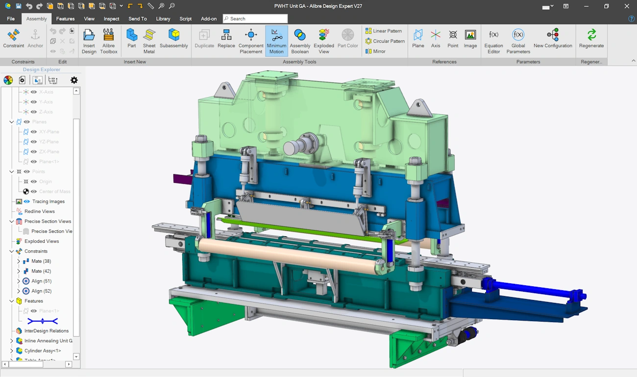
Assembly Overview Video
A dedicated workspace for assembly and top-down design of products.
You'll bring parts into an Assembly workspace and apply constraints, create logical groups of parts called Subassemblies, and ultimately result in a finished design.
From micro to industrial scale with full precision along the way
Building a Product from Components
Constraints are relationships between components and/or reference geometry that position or move components relative to each other. Two faces touch - a pin goes through a hole - 2 gears turn each other at certain rate - that kind of thing.
Constraints bring individual components together into an actual product. Standard constraints are focused on positioning and Mechanical constraints are focused on gears and pulleys.
Complex, Realistic Motion
After defining constraints, you can drag components of the model around and the motion will transfer accurately to other components.
Gears, pulleys, rack/pinions, and screws are special kinds of motion that have dedicated constraints, available in some versions.
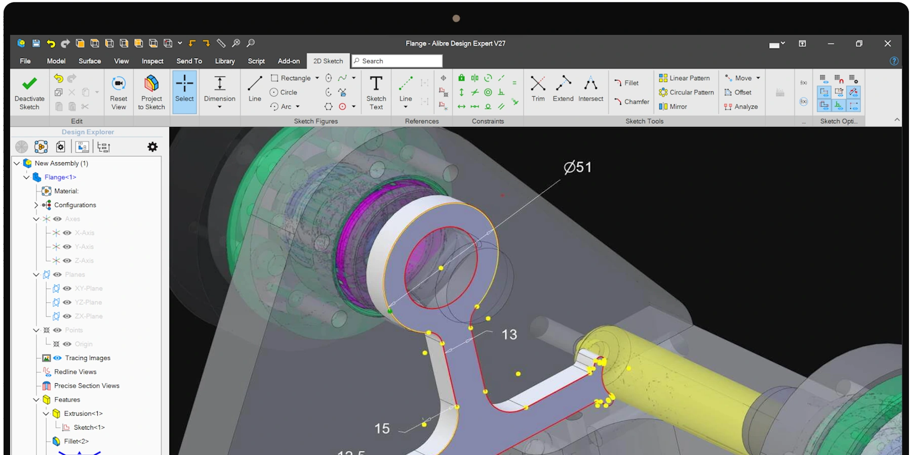
Bottom-up or Top-down Design
Create components individually or create them using other components as a reference.
Overlap Detection
Ensuring overlapping parts are corrected before a design is finalized is an important pre-production step. Interference detection checks for overlaps globally or between specified components.
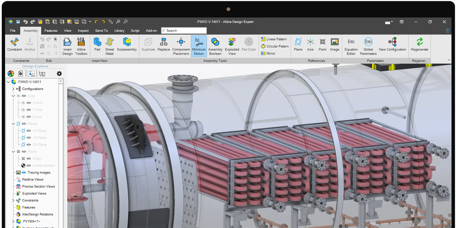
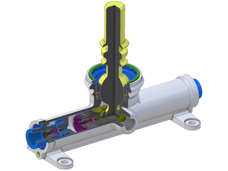
Realtime Sectioning
Section views are indispensable when analyzing a model to ensure proper fit but are also helpful for visualization in general. Realtime section views let you drag up to 3 planes with instant view feedback.
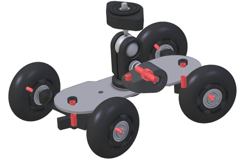
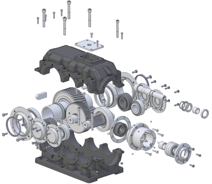
3D Exploded Views
Manually or automatically explode models to reveal the way the components come together and to give a clear picture of assembly.
Publish 3D exploded views into drawings with balloon callouts and BOM associativity.
Define explosion steps and publish an interactive 3D PDF document with animations.
Component Replacement
When changes to part requirements occur, you an easily swap one part or subassembly for another, with the ability to replace all instances or to select which to replace.
Other-Handed Components
Editable Mirror operations take advantage of symmetry in an assembly. In cases where a part is non symmetric, you can create other-handed parts automatically.
Patterns
Associative, editable patterns delete tedious repetition from your workflow. Select individual components or entire subassemblies as the basis for a pattern.
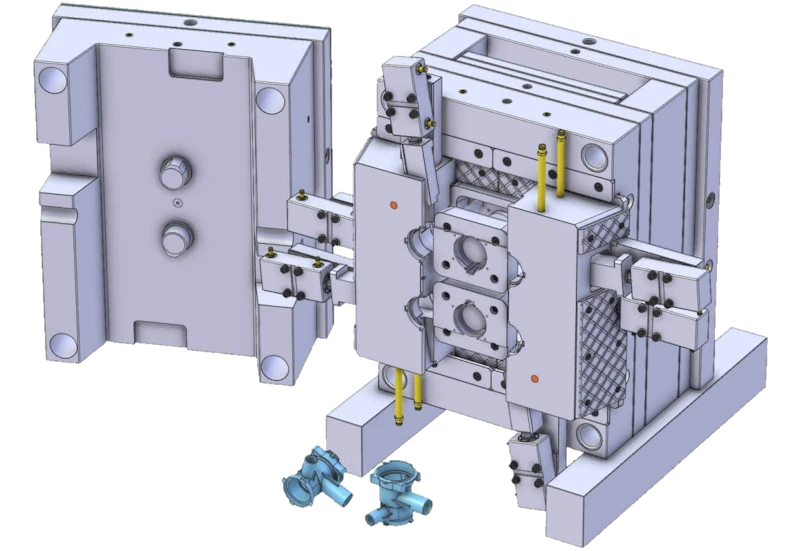
Assembly Booleans
Assembly Booleans combine multiple bodies into one body and/or subtract a body from one or more other bodies. This tool is critical to processes such as injection molding where the molded component must be subtracted from one or more cores and cavities.
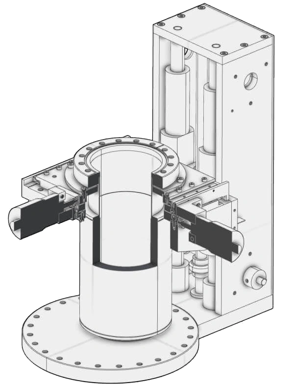
Illustration Mode
Enable the Illustration view type to turn the view into a style that looks like a 2D drawing. Use this style to rapidly reorient the model for screenshots.
You can also leverage the real time section views to have up to three active section planes.
These tools make creating instructions, manuals, and marketing materials easy and efficient.