Thanks for the reference to the topic, Ralf. It does work, but the process of top-down the way it currently exists for doing space structures is clumsy and way too complicated. I hope I can illustrate why with the following examples.
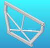
When you do space structures in contrast to machine design, you frequently start out with a basic layout and dimensions, or at least your first guess about what they should be. In the case of a car chassis, it may be the layout for the engine, passenger and trunk compartments. Frequently, this is done using bulkheads or at least some simple plane-like geometry that divides up the functional areas. The first graphic is just a quick idea of what I mean. It's a part file. Now, if you could have separable, individual pieces in the Alibre part file to put in drawings or run FEA analysis on, you'd actually be fine and could use assemblies in the traditional way to join the larger part "chunks" into a complete design.
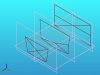
Now, if one could use this part file as a basic layout in an assembly and use the points and other geometry there to build individual parts (tubes or RHS parts typically in my work) you'd be fine and could make that a practical way to go. However, here is what happens when you load the part file with your layout geometry in an assembly:
Here I have the reference geometry turned on for the part file or otherwise you would see nothing at all. Notice the sketches and vertices (points) are no longer visible. You have nothing to use, really.
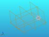
If I go to make a new part, hoping I can at least save the reference geometry from the base layout and maybe see the vertices when I do a 3D sketch, here is what you get:
Nada, zip, zilch, quacko otherwise known as total emptiness. You can't see the reference geometry in the new part file or the sketches, points, etc. This does not make it easy to do space structures in Alibre Design because neither part files or assemblies are friendly to this kind of thinking. You've got to start putting reasonably well developed parts into an assembly before you can really use the geometry to build other parts. This is truly putting the cart before the horse in this kind of design work. The parts typically are constructed to support the overall layout and flow from it. You don't start with the individual pieces and design the larger thing to fit those. Other 3D products do support design methods friendly to this kind of work.
As I said before, if part files in Alibre supported making individual elements (weldments in SolidWorks part files is one workable system) then that would work just fine and I wouldn't be writing this. But, right now Alibre Design does not work that way. Worse, you can't really lay these thing out in a part file even using 3D sketches with points and lines. You can see the 2D geometry from 3D sketching, but it does not work the other way round. Your 3D geometry is only useful for things like paths for sweeps and lofts. Although writing this reply just gave me an idea to try in part files using 3D sketches with 2D sketches built normal to their end points.
I'll try it out, but for right now, I'm not convinced there are good work-arounds for doing 3D space structures in part files. If I could program and use the Alibre API, I believe it could be done with what Alibre has built in to it. I did figure out the fundamentals of how SolidWorks does weldments when I had a license for that product, at least the construction part. Accessing the individual elements for drawings and analysis in Alibre might be difficult. I no longer have the C/C++ proficiency to do that kind of programming work though, or I might give it a try.
Cheers,