DBC
Senior Member
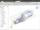
Alibre Design Expert 2019 doesn't seem to have a 3D Spline with Control Points tool. In a different forum folks have been taking about modeling the twisted fixture exercise seen here.

It is very easy in SolidWorks. Just a simple loft between two rectangles using tangency to face constraints.

I can do it in MoI using sweep with 3D Spline by Control Points guides in and in TurboCAD using loft with guides made with the 3D Spline by Control Points tool (central twist in MoI shown - looks the same in TurboCAD).

I have been trying in Alibre, but without the 3D Spline by Control Points tool it seems impossible. How would you do this exercise in Alibre Deign Pro 2019?

It is very easy in SolidWorks. Just a simple loft between two rectangles using tangency to face constraints.
I can do it in MoI using sweep with 3D Spline by Control Points guides in and in TurboCAD using loft with guides made with the 3D Spline by Control Points tool (central twist in MoI shown - looks the same in TurboCAD).
I have been trying in Alibre, but without the 3D Spline by Control Points tool it seems impossible. How would you do this exercise in Alibre Deign Pro 2019?
Last edited:


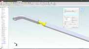


 It also has the Twist feature that can be used for something like this.


