What's new

Measurements to loft and shell edges

PaulProe

Senior Member
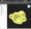
I am modeling a header flange with an adapter tube. Flange is a simple extrusion. The header tube is a loft with a shell applied to get a round tube on one end and a shape on the other end to fit the flange. I've put the two together in an assembly, then 3D print to verify fits and clearances.

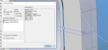
When I have an issue, I try checking the assembly and find I can not measure from a plane to any of the edges of the loft or the shell. I can measure from an edge of the flange to the loft or shell edge, but not from the planes.

To clarify this, I can measure from the opening flat of the flange to the outer flat of the loft and get .020". But if I try to measure from Axis<2> to the edge of the loft or the shell, I only get the perimeter of the edge, not a distance.

Is this an issue with Alibre? or am I doing something wrong

Paul
 

Attachments

  • Flange Assy.AD_PKG
    215.6 KB · Views: 9

Stu3d

Senior Member
I added some reference figures to the square part of the loft and could then measure from the flange to it.
 

PaulProe

Senior Member
Stu,
Thanks, I tried this and it resolved the issue, at least for this instance. Sounds like it is a 'less than optimal' performance on the coding of Alibre.

David & Max - your thoughts or comments

Paul
 

DavidJ

Administrator
Staff member
All I can say is that this seems to be a consequence of how Shell works. You don't seem to be able to select single edges of a shelled object.
 

idslk

Alibre Super User
Hello Paul,

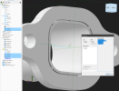
have you tried to select the outer face of the Header Tube and then an edge of the Header Flange?

1708020470981.png

Regards
Stefan
 

stepalibre

Alibre Super User
In situations like this I would make a projected sketch and measure from there. Or use reference geometry projected from the part. The edge is closed which is why the perimeter is given. You'll need to pick points or vertices to measure in this case. You can also check "Projected On Plane" and pick Plane<1>.

1708024619631.png

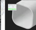
This is a limitation of Alibre's selection tools inside assemblies. Inside the part you can make a reference point at the tangent of the surface/edge.

1708025477323.png

Another option is to make a master sketch with your fit and clearance measurements built into the design. I don't use Alibre drawings but in general you should be able to measure from a drawing view as well.

Weldments:
You can build a part file with both the flange and tube included for weldment and casting type designs. If this will be welded, it would be easier to model in a part file. You can have an as welded configuration and or separate part files to represent piece parts for the assembly.
 

Attachments

  • Flange Assy_SSM.AD_PKG
    217.8 KB · Views: 0

stepalibre

Alibre Super User
I forgot to include the example:
1708030000340.png
This applies to any fabrication method. You should be able to measure how you want in the weldment part.
 

Attachments

  • Flange Assy-With-Weldment-Example.AD_PKG
    421.9 KB · Views: 0
Last edited:
Top