What's new

Cutting a part into two parts

Hilmi

Member
Hi,

I have designed a part and want to cut it and split it into two separate parts so I can modify the part for inserting a captive bolt on one end for a moveable jaw. The other part I am not able to figure out is I created the first part, then created an assembly to add other parts. Now I can't rename the assembly nor can I rename the new part I added in the assembly. sort of confused as right clicking on the tree is not giving the option to rename.

I have managed to figure out most functions of Alibre cad on my own, but this one I have not managed to figure out. I am using version 27 Pro.

Edit: have found the split tool, but I haven't figured out how to create a plane through the part to split it, sorry for the very dumb question, but we all got to start somewhere

Thanks
 

Ex Machina

Senior Member
Hi,

I have designed a part and want to cut it and split it into two separate parts so I can modify the part for inserting a captive bolt on one end for a moveable jaw. The other part I am not able to figure out is I created the first part, then created an assembly to add other parts. Now I can't rename the assembly nor can I rename the new part I added in the assembly. sort of confused as right clicking on the tree is not giving the option to rename.

I have managed to figure out most functions of Alibre cad on my own, but this one I have not managed to figure out. I am using version 27 Pro.

Edit: have found the split tool, but I haven't figured out how to create a plane through the part to split it, sorry for the very dumb question, but we all got to start somewhere

Thanks
If you want to split a single part into two and use them in an assembly, your best bet is to use configurations. Cut the part so the one piece you want remains. Now create a second configuration, check the "Feature Suppression" checkbox, suppress the cut you just made, and make another one cutting the other piece.

But, generally speaking, if you want to make 2 parts that reference each others geometry, start an assembly file and create new parts in there. Not in a single part file. A single part file, should always be treated as a single part file.
 

Hilmi

Member
Hi,

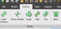
I am using an assembly, I still don't understand how to actually perform the cut. I am attaching two screenshots. One shows the split tool I found that HaroldL was asking about and the other shows the part that I want to cut in two (highlighted in blue). The split tool I found, I can't figure out how to use and I suspect its actually the wrong tool.
split tool.png

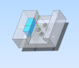
I basically want to split that part in two, model some alignment features and put a cut out for a captured nut to be installed on the inside so that the jaw can be moved via thumb screw.
Clamp.png
 

Hilmi

Member
I found this thread from 2006, but it is very old and might not even be relevant anymore, in terms of computer software that is a very long time.

I also don't really understand the work around that was explained there. Surely there is a simple way to just create a reference plane offset from the back face of the part and then shift the plane to the desired location and selecting split part along plane? This is how it is done in fusion 360, simple and straight forward.
 

dwc

Alibre Super User
I also don't really understand the work around that was explained there. Surely there is a simple way to just create a reference plane offset from the back face of the part and then shift the plane to the desired location and selecting split part along plane? This is how it is done in fusion 360, simple and straight forward.

I am not sure where your problem lies. As you say it is very simple, just not exactly the same as some other program.
Add the plane on which you want to cut to the part.
Make two configurations of your part. In one configuration you do a extrude cut from one side of the plane, in the other configuration from the other side.
You now have two parts that you can use as you wish. You can also add all the other features you need after the split in the configuration.
Those parts are called PartName<config1> and PartName<config2> (or however you decide to rename them).
If you set the locks correctly any changes you make in the base part will automagicly filter down to the other configurations.

This is standard operating procedure and something I do often. I often end up with 5 configs,
1)the whole piece for modeling (which is too big to 3Dprint on my printer), 2)subpiece1, 3)subpiece2,
4)subpiece1-with special supports for 3D printing, 5)subpiece2-with supports for 3D printing.
The big advantage of configs is that you can do what you want to the parts, you are not limited to split on a plane. You can split on any geometry you like and continue from there.
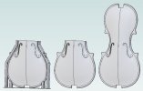
Below an example, from right to left the configurations: BasePart, PartLower, PartLowerPrintable

Configs.JPG
 
Last edited:

DavidJ

Administrator
Staff member
The 'Split' tool you found is specifically for SURFACES (note it appears on the Surface tab of the Ribbon).

There is no split tool for solids - you'll have to cut away one or other portion of the part and 'Save As' (as you don't have Configurations in Professional).

I.E. in the current file cut away one half with an extrude cut or thin wall extrude cut - then Save As. Next edit the cut just done to remove the other portion of the part and Save (or Save As if you want a different name).

EDIT - the thin wall cut is particularly good for this, as you can simply change which side of the same sketch line the cut takes place on for each of the two variants.
 
Last edited:

Hilmi

Member
Hi,

Thank you for your input on how this is done. I will now try to find some videos on the think wall cut tool so I can better understand what you are trying to explain to me.
 

DavidJ

Administrator
Staff member
Some information on Thin Wall Cut at

Simply sketch a straight line in a sketch to define the split line (use dimensions or constraints to fix its position). Apply Thin Wall Cut with a large value for Wall Thickness in the 'Side 1' field (large enough to cut away everything on that side of the line).

Save As the the file - now edit the Thin Wall Cut - swap over the values in 'Side 1 and 'Side 2' and regenerate to last feature. Material should now be cut away on other side of the line - Save As.

You now have 2 files each with a different half cut away - because the same sketch line was used in both, the parts must join up perfectly.
 
Top