What's new

Re-Usable geometry

This may take a little explaining so apologies first. Real world projects are best for learning so I've been using AD Expert to design dust collection adapters for my wood shop stationary equipment. Now I want to move onto the portable and hand held tools and want to develop a bayonet adapter for a single connection point for multiple tools. I'm very comfortable with configurations and am thinking of using them for the adapting side, having the bayonet geometry fir the base feature with the adaptive side for each tool defined by each configuration.

The up side is that there is one place to adjust when making changes for fit and function on the bayonet side along with having a single file to add new adaptive configurations. One down side is one file contains everything and if it gets broken all can be lost. The soon to be released pdm system may help with those fears and I'm very diligent about versioning when making large changes, but all the eggs in one basket is not just a warning.

Does this seem like a reasonable path and is there another option which might serve as well? I've learned a lot from long time users on this forum and hope to get enough experience to be more than just a lurker. ;)

Thanks in advance for any replies.
 

NateLiquidGravity

Alibre Super User
Configurations could be used but the part file will only have one file name and one icon. I would make the base geometry in a separate part that is inserted into your adapter parts as a Boolean feature. Then make a new part for each adapter. That way the base geometry can be edited separately and any changes in an adapter part won't affect the base geometry or any other adapter part.
 
Hey Nate, thanks for the reply. Boolean's are something I thought of shortly after hitting post. I've played with them but haven't had a real world use for them yet, but it sounds like this will be the perfect chance as I have time this weekend. Are there any caveats with using them as far as updates, etc.? Thanks again.
 

NateLiquidGravity

Alibre Super User
Using boolean features - all changes to the boolean tool parts will propagate through when the file is opened. And like any other things those changes can break things depending on where in the part history you put it and how you build to it. For example if you remove a face in the boolean tool part then any fillet that was using that face can break.
 
Thanks @NateLiquidGravity , a combination of configurations and boolean unite features is going to help standardize and control designs like I didn't think possible. Every time I learn something new in AD the more impressive the software gets and the quick responses on this forum saved a lot of development time. Not 100% sure about the update when changes are made to the origin of the boolean features but I read on the forum something about commit and hitting F5, neither of which worked until the target part was added to the assembly. Will have to read the docs more.

Thanks again.
 

DavidJ

Administrator
Staff member
If you have a part containing a boolean open, then separately open the boolean source, you now have 2 separate instances open in memory from the one file on disk. Changes in one memory instance won't show in the other, and what's more if you save files in the wrong order you can lose changes too.

Generally best not to have both open at the same time...
 

DavidJ

Administrator
Staff member
I am saying that if you have more than one instance of the same file open, there is scope for confusion and even data loss if editing.

Examples include
* Editing a separate instance of a part file, when the assembly it is contained in is also open ( to avoid problems use 'edit here' or 'edit in separate window' from the assembly then you are working with a single instance of the file).
 

HaroldL

Alibre Super User
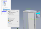
Be aware that there is no way to edit the Boolean tool in the the Boolean feature, there is no RMC Edit option.

1710130357054.png

So, if the tool needs to be modifed you should close the part file containing the Boolean feature, edit the Tool part, then reopen the part file with the Boolean feature and it will have the updates applied to the Boolean tool part.

It would go a long way of making Booleans a more useful if you could edit the tool parts similar to the Edit Here or Edit in a new Window option that assemblies have. And I'm not sure what kind of programming machinations need to take place to implement that feature.
 
Had a chance to play with boolean add some more, and this workflow seems to be best for what I'm trying to accomplish.

1. Created an assembly with both sides of the bayonet in a base configuration.
2. Opened the file for the tool side connection and did a boolean add of the require bayonet side to complete the design.
3. Added a configuration to the assembly for the tool side connection and added the model to the assembly. Location is not important for the intent.
4. Repeated steps 2 and 3 for another tool side connection.

After this was done an obvious un-needed change was added to the boolean add model in the context of the assembly, just for testing purposes. In the world of one ring to rule them all, this procedure updated every model with the boolean add in the assembly to include the modification at the same time, which is the intent in this case.

With all the help from forum members this is how I figured it would work, and it is very impressive.
 
A question for experienced users. I have two options with using assembly boolean in the design process. The current design is a bayonet adapter for dust collection with the male end having many different configurations, one for each of the power tools that create dust. The female end is mostly static with only a few configurations.

If all male configurations are in a single file, and there is no way to group features in version 27 of AD, renaming is the only way to identify which feature belongs to which configuration. The second option would be to create a separate file for each configuration to keep feature list simple. This is then the question of a lot of features in a single file or a large number of simpler files, each has advantage.

The main consideration for me would be making sure that updates get pushed to the right files when changes to the base parts are made. Right now a master assembly is being used where ALL files are assembled, including the files with the base parts used in the assembly boolean.

Has anyone developed any preferences they'd like to share.
 

DavidJ

Administrator
Staff member
I'd comment that using an assembly boolean and wanting updates to get pushed to right files are not compatible. Assembly booleans don't update if the source files are edited.

Most of the time I use Part booleans as these will update if source files are edited.


Doesn't selecting configuration show clearly which features belong to it, or do you want to instantly see that (say) Cut3 is used in configs 1,4,6 & 7 ?
 
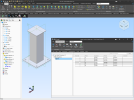
Hi David, thanks for the response, the boolean type is in an image below, and thanks to all the help from the forum giving me a good handle on updates. However, the description of the question may be unclear. It's looking like the file with configurations will have several dozen variations. Is there a point where configurations can get difficult for AD to handle? That was one question I didn't state well if at all.

To answer my own main question, I'm thinking of going with separate files instead of all configurations in one file. Giving it more though it comes down to all the eggs in one basket scenario, if the one file becomes corrupt everything is lost, whereas if one file with one configuration gets corrupted everything else is good. To geek out a little here, if the One Ring is destroyed all the others are powerless. LOL
 

Attachments

  • Capture.PNG
    Capture.PNG
    3 KB · Views: 7

stepalibre

Alibre Super User
All options have tradeoffs. The files that's used to generate or develop your parts don't necessarily need to be the same files used in the final assembly. You could save as or export the configurations as standalone parts (with a good naming convention) to be used in your assemblies.

bayonet adapter main part with configurations - bayonet-adapters.AD_PRT
- type 1 (male end cap)
- type 2 (male hose)
- type 3 (male brush)
- type 4 (male extension)
- type 5 (male coupler)
- type 6
- ...

Exported configurations to part files:
bayonet-adapter-type1.AD_PRT, bayonet-adapter-type2.AD_PRT, bayonet-adapter-type3.AD_PRT

You could still interchange the main configuration part (bayonet-adapters.AD_PRT) with the standalone exported parts (bayonet-adapter-type3.AD_PRT, etc) since they are the same geometry.

The result from the assembly boolean can also be used as a development file that is then exported and assembled inside another final assemble file. This is common in weldment type designs where you have multiple steps or processes the models need to go through before its done. Alibre doesn't have multi-body parts and other features that make mold and weldment design possible or easier. Part and assembly booleans are the alternative but they are not the same.

If all male configurations are in a single file, and there is no way to group features in version 27 of AD, renaming is the only way to identify which feature belongs to which configuration.
I agree with you here. It can be difficult to separate features and understand the relationships between them in the feature tree when you have many configurations.

Example:
You can use scripts and the API to export configurations as part files. I have spaceframe weldment components and a growing list of configurations that I'll export as parts to use in assemblies.

1716236869798.png

The configurations aren't all real sizes but are used in the design/development process. I won't use the AD_PRT with the configurations, it's used as a library file not to be used as the final part file. The spaceframe weldment can be 1 of 1000's, you will never change the length one by one. The length is the only variable dimension. They are all assembled with code and the configurations add some overhead, so using simpler files is best. Many CAD library systems work this way, they generate configurations, the chosen size is saved as a standalone part file that's added to the assembly, instead of the part with all the configurations.

Is there a point where configurations can get difficult for AD to handle?

I guess my point is it all depends on what you're building and what your process and end goal is. Alibre is lacking features that makes configuration design easier and scalable for more complex projects. Without using the API, It's basic compared to other 3D CAD tools.
 
Last edited:
The male part of the adapter has the interface area as the base feature because it never changes, with some rather interesting transitional features using loft for one. These features can be renamed so they are easily identifiable in the tree belonging to a specific configuration.
Exported configurations to part files:
I didn't find an AD command or script for exporting configurations except to a neutral format like stl or stp. Could you please elaborate on exporting configurations?

tia
 

stepalibre

Alibre Super User
If the models are simple like my spaceframe weldments, exporting to STEP is perfectly fine. Importing a STEP file creates a part with the STEP model embedded. It can be more performant than AD_PRT native files but this all depends on your geometry and assemblies. You'll need to run some tests on your geometry to understand the difference STEP vs configs vs simple parts. I don't see much difference with simple geometry.

Using the API I export configs to STEP and using a naming convention can match those exported files back to the parent. I use part Booleans to merge or assemble the exported STEP files back into a single part where updates can be made. One example is holes that need to be cut in the tubes, I use part booleans instead of building the hole into the part. Galvanizing holes are not needed in the base design but are needed for detailing. This keeps the part simple.
I also create assemblies, so there's more to the story.
1716245313437.png
 

stepalibre

Alibre Super User
Another variation is part booleans with global configurations. This is where part and assembly booleans shine and is better than multi-body part workflows.

1716269935085.png

This workflow is more performant, at least in my work, than using assemblies.
 

Attachments

  • support_column_design_type_1.AD_PKG
    131.7 KB · Views: 0
Last edited:
Top