jcdammeyer
Senior Member
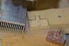
I have to create a customized heatsink from extruded stock. I designed the stock with the stock outline on the XY plane and extruded to the heatsink height. One sketch to remove some of this extruded section for a clearance.
Then a series of repeated rectangles and cut down to a bit a above the XY plane and bingo there was my ribbed heatsink stock with a notch in the ribs.
Now flip it over and create both pockets and posts on the bottom which results in material below the XY plane (-Z direction) and pockets above it (+Zdirection)
I've been able to use my 2017 AlibreCAM to create both the pockets and and the profile the outline out of the stock. But the 2 1/2 axis facing just isn't working. It puts a 0.125 tool into a 0.089 hole. It runs into one of the extruded pads but leaves a larger gap around round posts.
I've run into this before and usually played around until it's sort of fixed but this time playing doesn't work. I'd like to write myself a tutorial so when I want to do this I can refer to what worked before. If I can get it to work.
The steps would be I think:
1. Orient the Machine Tool rotating Z around X so when simulating the tool bit is above the work which is also mounted upside down in the vise.
2. Surface first setting the correct machining regions.
3. Select tool and other parameters
4. Generate tool path.
I've attached the part. What am I doing wrong?