NateLiquidGravity
Alibre Super User
This tutorial is now obsolete since you can now build the loft as a regular solid part and then use the Convert to Sheet Metal button.
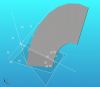
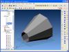
Here is a sample octagonal reducer.
1: First draw the two polygons one above the other on different planes. I assume you can do these yourself.
2: Then go around each point while in the sketches and add all the 3d points from the Sketch>Insert>Point one at a time. :roll:
3: Then add a couple planes adjacent to each other around the outside so you can get the angle to make the bends with the measurement tool (you can turn up the part tolerances in the part properties if you need to).
4: Next make the Tab sketch on one of those planes and constrain it to the 3d points.
5: Measure the angle between the two planes for the next bend.
6: Now add a flange checking inside alignment and outside leg with the angle found above.
7: Edit the sketch of the new flange by removing the constraints of the 3 outer sides.
8: Now constrain them to the 3d points for that side.
9: Repeat starting at step 5 until no more bends are required.
Give it a look and let me know if anything else that needs to be explained in this how to.
As you may note there is a small difference in diameter when you get all the way around. This is a rounding error for the angles of the bends (the gap between the start and end is intentional). This is barely noticeable and will not cause any difference in my line of work.
I plan to release a new "How To: Complex Sheet Metal: " every so often. Let me know if you have any ideas you would like to see done.
The next example is How To: Complex Sheet Metal: Octagonal To Rectangle at Skew
Attachments
Last edited: