What's new

How To: Wrap Text Around A Cylinder

NateLiquidGravity

Alibre Super User
Here is a simple example of wrapping text around a cylinder.

Note:V12 has added text in a sketch. If you use an older version you will have to create the text in the sketch on your own. You can use Alex Franke's Text Import Wizard Or DeskEngrave Or if you have a full version of AutoCAD you can use the Express Tools Text Explode tool and clean that up.


1: Start a sheetmetal part.
2: Draw a rectangle and make a tab out of it.
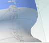
3: Add flanges with the curve you want to match what you want to wrap around.
4: Do an Unbend to all flanges.
5: Create a sketch on the outside of the unbent part.
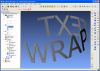
6: put the text in the middle and a box around the text that goes all the way across the start tab to all the way across the last flange. A strip must be left on the top and bottom of all the material for it to form the letters correctly.
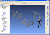
7: Rebend All
8: Create a sketch on one of the standard planes.
9: In the sketch create two rectangles. One to cover the entire top strip and another to cover the entire bottom strip.
10: Extrude Cut Through All.

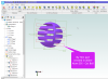
This can now be added to the outside or subtracted from a cylinder.

Give it a look and let me know if anything else that needs to be explained in this how to.

I plan to release a new "How To:" every so often. Let me know if you have any ideas you would like to see done.
 

Attachments

  • WRAPTEXT.PNG
    WRAPTEXT.PNG
    93.3 KB · Views: 373
  • WRAPTEXT.stp
    842.7 KB · Views: 337
Last edited:

mstacy

Member
Nate,

"Cutting" the text (Cut<6> in the sample file) through the sheet metal is the step that I couldn't figure out from your text description. But that makes sense after looking at your example. How did you make the letters in Sketch<6>? Is there some sort of annotation or text tool to sketch block letters? Otherwise sketching the letters from arcs, line segments, etc seems quite cumbersome to say the least.

Regards,

Matt
 

NateLiquidGravity

Alibre Super User
Hi Matt,
The current version of Alibre doesn't have a tool to make text outlines in sketches. The next version - Alibre Design v12 will have a tool to do just that.
NateLiqGrav said:
Note: You will have to create the text in the sketch on your own. You can use Alex Franke's Text Import Wizard Or DeskEngrave Or if you have a full version of AutoCAD you can use the Express Tools Text Explode tool and clean that up.
 

jordanyte

Member
Hi,

I'm trying to do something a little bit similar.

I have a cylindrical part (an electrolytic capacitor) which has a crimped body - I made that with a basic cylinder and a revolved cut, and fillets:


Now I want to mark the negative terminal with text, which has to conform to the surface longitudinally.

Capacitor manufacturers actually start with an aluminium can and then put a thin, pre-printed heat shrink type plastic over it, so there's almost no thickness to the text.

How would I do this in Alibre? I can't seem to figure it out. I want the text to conform to the surface as if it were screen-printed.

Thanks for any guidance you may be able to give.

Ben Jordan.
 

Attachments

  • Electrolytics.png
    Electrolytics.png
    45.1 KB · Views: 94

jhiker

Alibre Super User
You could put the text (or negative symbol) on a plane 'just' outside the diameter of the capacitor and extrude it to the OD - then use an 'extrude cut' (e.g. sketch two concentric circles) to shave it almost to, but fractionally larger than the OD of the capacitor.

I'm sure there are other ways, too...
 

jordanyte

Member
Ah yep, understand. I'll give that a shot.

I think I originally tried something like that but got frustrated with getting the cut geometry properly closed.

I was going to do a circular cut around the cylinder circumference (i.e. perpendicular to what you mentioned) to trim the text back to the surface.

I'll try it again - I guess I was hoping for something a little easier :)

Thanks,
Ben.
 

neilr

Senior Member
I shelled the capacitor and then cut the words then did a rev.boss to fill in the capacitor...you can skip the shell I realized as I did it.
 

Attachments

  • words.png
    words.png
    200 KB · Views: 137

jordanyte

Member
Hi,

I'm trying to do something a little bit similar.

I have a cylindrical part (an electrolytic capacitor) which has a crimped body - I made that with a basic cylinder and a revolved cut, and fillets:


Now I want to mark the negative terminal with text, which has to conform to the surface longitudinally.

Capacitor manufacturers actually start with an aluminium can and then put a thin, pre-printed heat shrink type plastic over it, so there's almost no thickness to the text.

How would I do this in Alibre? I can't seem to figure it out. I want the text to conform to the surface as if it were screen-printed.

Thanks for any guidance you may be able to give.

Ben Jordan.
 

tonymaden

New Member
Hi all, I really am a complete noob at Alibre, and am using the Atom 3D product. I need to add text on a cylinder or sphere surface but do not know if it is possible with Atom or only in Design professional. I need to add brand logo in text to top of our cat bell ball. Thanks for guidance/helps, and happy thanksgiving!
 

Attachments

  • catballbell.png
    catballbell.png
    198.3 KB · Views: 26

bigseb

Alibre Super User
Hi all, I really am a complete noob at Alibre, and am using the Atom 3D product. I need to add text on a cylinder or sphere surface but do not know if it is possible with Atom or only in Design professional. I need to add brand logo in text to top of our cat bell ball. Thanks for guidance/helps, and happy thanksgiving!
Tony, I already responded to your pm. Long story short: Moi.
 

HaroldL

Alibre Super User
You cannot sketch on the surface but you should be able to extrude text to the ball then trim it to the same or offset radius ball.

Create an offset plane.
Sketch on that plane to add your text.
Extrude To Geometry.
Sketch a profile on a perpendicular plane and Revolution Cut to trim the text to size.

You will need to Project to Sketch the sketch for the ball profile as Reference Geometry in order to apply a concentric constraint from the Revolution profile to offset the radius for trimming the text.

Text on Ball.png
 
Top