GIOV
Alibre Super User
Alibre Design Future Improvements:
1. - Main open office Spreadsheet (Excel) able to be linked to entire model assembly, sub assemblies and parts with ability to be update all design automatically.
2. - Project to Sketch for assembly, sub assemblies and parts:
To have a new Inter designs project to sketch maintaining association with source entity from a new design explorer function like section view that right now doesn’t have this capability.
3.-Assemble Work space:
3.1.-The main equation editor must have access to all subs assemblies or parts equation editor by links,
3.2.- The Design Explorer must include all sub assemblies and parts;
3.3.- Import txt point files as insert points (reference geometry); Done")
3.4.-The Toolbar Orient View needs add a two arrows to pitch the drawing easily upwards and downwards;
3.5.- Constraint Limits. Done;
3.6.- Symmetric Constrain;
3.7.-Triad Tools in one click and to be parametric for rotate and move the Part or Sub-Assemble;
3.8.- 2D and 3D Sketches for applied constrain to be a Part or Sub-assemble movement guide.
3.9.- Equal Segment Curve's divide with node (ref) points.
4.-Part work space:
4.1.- 2D Sketch
4.1.1. - Figure offset should be included into equation editor;
4.1.2. - Insert Plane should be included into equation editor;
4.1.3.- Import txt point files as insert points (reference geometry).
4.14.- Equal angle Constraints.
4.15.-Equal Segment Curve's divide with node (ref) points.
4.16.-Project to Sketch's History to find and modify the linked one.
4.2 - 3D Sketch:
4.2.1. - To have the same capabilities of 2D Sketch on the set plane;
4.2.2. - To included Surface and thicken generation;
4.2.3. - To have the same or better capabilities of Rhinoceros 3dm or/and ThinkDesign;
4.2.4. - The Toolbar Orient View needs add a two arrows to pitch the drawing easily upwards and downwards.
4.2.5.-Equal Segment Curve's divide with node (or ref) points.
4.2.6.-Project to Sketch's History to find and modify the linked one.
4.3.-Parts Feature:
4.3.1.-Solid Parts (casting)
4.3.1.1.- Mirror Chamfer & Fillet Feature;
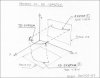
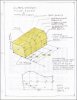
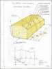
4.3.1.2.- Feature Chamfer with intermediate measures as show in the drawing below;
4.3.1.3.-Feature Fillet with intermediate measures as show in the drawing below;
4.3.1.4.- Feature Loft Boss improvement to obtain more accurate body and shell of the part. Right now is so limited.(Important);
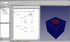
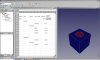
4.3.1.5.- Feature Section View> tools> area Properties like Area centroid, Area Moments;
4.3.1.6.-WorkSpace Sheet Sheet metal > Feature Contour with Loft (3DGuide Curves if necessary);
4.3.1.7.- Copy Features with its Sketches from design explore and paste into another part.
4.3.2.-Sheet (Metal) Part
4.3.2.1.-Loft between two sketch able to be developed.
4.3.2.2.-Feature Section View> tools> area Properties like Area centroid, Area Moments;
5.- Drawing work space:
5.1. - Include Area Properties as Region Properties like Area centroid, Area Moments;
5.2.- Equal angle Constraint
6.-Design Explorer:
6.1.-Inside of Design Explorer as feature, so copy an Specific sketch and paste in another sketch the drawing with its constraints and the possibility of Maintain association to Source Entity without enter to the sketch in the Design WorkSpace. This feature give the option of Project to Sketch between perpendicular planes too.
7. - Develop workbench;
8 - To have a console likes python to special user task; Done
9. - Improve the Menu language than graphic, for access to the special task without big ribbon space;
10.- Improve memory management. (Ex. import 3D Points from txt file take so much time). Done by Stefan Script
May be some of this features described above have been included into the last version.
Thanks

1. - Main open office Spreadsheet (Excel) able to be linked to entire model assembly, sub assemblies and parts with ability to be update all design automatically.
2. - Project to Sketch for assembly, sub assemblies and parts:
To have a new Inter designs project to sketch maintaining association with source entity from a new design explorer function like section view that right now doesn’t have this capability.
3.-Assemble Work space:
3.1.-The main equation editor must have access to all subs assemblies or parts equation editor by links,
3.2.- The Design Explorer must include all sub assemblies and parts;
3.3.- Import txt point files as insert points (reference geometry); Done
3.4.-The Toolbar Orient View needs add a two arrows to pitch the drawing easily upwards and downwards;
3.5.- Constraint Limits. Done;
3.6.- Symmetric Constrain;
3.7.-Triad Tools in one click and to be parametric for rotate and move the Part or Sub-Assemble;
3.8.- 2D and 3D Sketches for applied constrain to be a Part or Sub-assemble movement guide.
3.9.- Equal Segment Curve's divide with node (ref) points.
4.-Part work space:
4.1.- 2D Sketch
4.1.1. - Figure offset should be included into equation editor;
4.1.2. - Insert Plane should be included into equation editor;
4.1.3.- Import txt point files as insert points (reference geometry).
4.14.- Equal angle Constraints.
4.15.-Equal Segment Curve's divide with node (ref) points.
4.16.-Project to Sketch's History to find and modify the linked one.
4.2 - 3D Sketch:
4.2.1. - To have the same capabilities of 2D Sketch on the set plane;
4.2.2. - To included Surface and thicken generation;
4.2.3. - To have the same or better capabilities of Rhinoceros 3dm or/and ThinkDesign;
4.2.4. - The Toolbar Orient View needs add a two arrows to pitch the drawing easily upwards and downwards.
4.2.5.-Equal Segment Curve's divide with node (or ref) points.
4.2.6.-Project to Sketch's History to find and modify the linked one.
4.3.-Parts Feature:
4.3.1.-Solid Parts (casting)
4.3.1.1.- Mirror Chamfer & Fillet Feature;
4.3.1.2.- Feature Chamfer with intermediate measures as show in the drawing below;
4.3.1.3.-Feature Fillet with intermediate measures as show in the drawing below;
4.3.1.4.- Feature Loft Boss improvement to obtain more accurate body and shell of the part. Right now is so limited.(Important);
4.3.1.5.- Feature Section View> tools> area Properties like Area centroid, Area Moments;
4.3.1.6.-WorkSpace Sheet Sheet metal > Feature Contour with Loft (3DGuide Curves if necessary);
4.3.1.7.- Copy Features with its Sketches from design explore and paste into another part.
4.3.2.-Sheet (Metal) Part
4.3.2.1.-Loft between two sketch able to be developed.
4.3.2.2.-Feature Section View> tools> area Properties like Area centroid, Area Moments;
5.- Drawing work space:
5.1. - Include Area Properties as Region Properties like Area centroid, Area Moments;
5.2.- Equal angle Constraint
6.-Design Explorer:
6.1.-Inside of Design Explorer as feature, so copy an Specific sketch and paste in another sketch the drawing with its constraints and the possibility of Maintain association to Source Entity without enter to the sketch in the Design WorkSpace. This feature give the option of Project to Sketch between perpendicular planes too.
7. - Develop workbench;
8 - To have a console likes python to special user task; Done
9. - Improve the Menu language than graphic, for access to the special task without big ribbon space;
10.- Improve memory management. (Ex. import 3D Points from txt file take so much time). Done by Stefan Script
May be some of this features described above have been included into the last version.
Thanks
Attachments
Last edited: