I needed simple internal tooth gears for planetary gears so I personalized SpurGear_MAKER further. Everything else out there cost a fortune, has to be exported, imported, copied, pasted and/or otherwise involves a lot of time and processing.
It seems sufficient for my current needs.
A little explanation of my preferences might help.
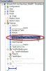
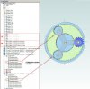
B C - For a part like this, all Configurations unlocked allows changes such as tooth count to propagate to all configurations. This allows selecting a configuration in an assembly without opening the part to edit.
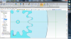
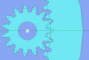
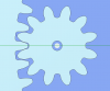
B - The simple spur gear with variants on the display properties.
C - A simple "internal" tooth variant.
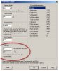
E - The "Equation Editor" is still flakey enough that I avoid direct access as much as I can (it is still SBD). I create a set of planes above the part to update and store what variables I can. It is important to note that in "design explorer" although the name of features are incorrectly grayed out, they are still active and editable as the icons colorization reflects (much as bold and highlighted features are still often in error).
F - These are extra values only used in generating an internal tooth gear.
G - This feature set is active when a simple spur gear is selected in configurations.
If you select a "B, C or D" configuration in section B Configurations, you never need to suppress or unsuppress these features directly (and doing so in this section will mess up configurations).
H - This feature set is active when a simple internal tooth gear is selected in configurations.
If you select a "B, C or D" configuration in section C Configurations, you never need to suppress or unsuppress these features directly (and doing so in this section will mess up configurations).
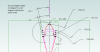
I - Here you can suppress or unsuppress the feature directly for a "tooth aligned" or "half tooth aligned" key slot. The selection here will reflect in all configurations. I could have moved this section just below section Ffor clarity.
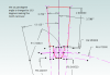
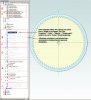
J - Again using "planes" I created a section where you can enter the "radius" from another gear in "Enter 2nd Gear Pitch Radius" and read the result in "Calc 1 and 2 Gears Offset" to determine, or just keep a record of, the axis offsets with another gear. This is a rare occasion, where to read the result, you will need to "edit" "Calc 1 and 2 Gears Offset" and select the "f(x), Equation Editor" to see the answer.
The file is a bit large. But deleting redundant sections, for a new part as an example, actually "increases" the size from 2.59 MB to 8.4 MB :roll: . If you want a smaller part file without configurations or history you can export as a STEP(214) and import to bring it under 1 MB.
")