What's new

Constraint help

gld

Member
I have here a cylinder head with 2 values, valve guides, and one rocker arm. I have been working for the last 3 evenings trying to put this rocker arm in its proper place. When I apply a constraint to lineup the face of the washer on the rock arm with the inside of the support I get an error. I don't understand why.
 

HaroldL

Alibre Super User
Gary, When uploading an assembly or drawing please create a Package file and upload that file. A Package file will collect everything associated with the assembly or drawing so there won't be any missing file errors when downloaded and opened.

From the File menu:
1675731648939.png


From the File ribbon:

1675731687125.png
 

Nick952

Senior Member
The side faces of the Rocker Arm are not 90 Deg to the pivot bore, causing conflicts between a Concentric constraint for the pivot and a Coincident constraint to the upright face.

Just checked your Rocker Arm model and it appears that Sketch<3> and its associated Extrusion<6> are the problem.

Constraining the arm using a Concentric constraint between the Pin and bore, then using the Reference Geometry for both the arm and pin, a Coincident constraint between planes works (As in the Attached Package). However the Rocker Arm model still needs correcting.
 

Attachments

  • Cylinder head_sheet17 - Nick.AD_PKG
    675.1 KB · Views: 15
Last edited:
  • Like
Reactions: gld

gld

Member
The side faces of the Rocker Arm are not 90 Deg to the pivot bore, causing conflicts between a Concentric constraint for the pivot and a Coincident constraint to the upright face.
Just checked your Rocker Arm model and it appears that Sketch<2> and its associated Extrusion<6> are the problem.

Constraining the arm using a Concentric constraint between the Pin and bore, then using the Reference Geometry for both the arm and pin, a Coincident constraint between planes works (As in the Attached Package). However the Rocker Arm model still needs correcting.
Nick; I'll recheck the angles.

Thank you
 

idslk

Alibre Super User
lines in rocker arm sheet20 sketch<3>are only approximately parallel to the sideface due to they are not constrained...the result is:
1675787238577.png
Regards
Stefan
 

gld

Member
OK, I corrected the error in rocker arm sketch 3, and reloaded into assembly. In the process I did something too screw it up good. Can not constrain any thing.
I have no idea what I did to mess this up. I am ready to rebuild this from scratch.
A big thank you too all who are trying to help me.
 

Nick952

Senior Member
I feel your pain, been there and done that.

Last night after my afternoon shift at work, I had another look and also corrected your Rocker Arm model.
I Aligned all of sketch<3> with the first extrusion and made sure that it was fully constrained.
Finally in the Head assembly, I changed the Rocker Arm side constraint from a Plane Coincident to coincident with the upright.

Attached is a package of this revision, so should get you back on track (Or use the package from my earlier Post, if you want to do the correction yourself).

Delete your old files, download this one and open the assembly, then use "Save As" to change the assembly title removing my "- Nick - Rev1" additions. If you're unsure about doing this, let me know and I'll create another package with this removed for you.

Edit:- Removed Reference to incorrect sketch (Sketch <2> should have read Sketch<3>)
 

Attachments

  • Cylinder head_sheet17 - Nick - Rev1.AD_PKG
    680.9 KB · Views: 7
Last edited:

Nick952

Senior Member
Hi Stefan,

Yes you are correct, I should have stated Sketch<3> and its associated Extrusion<6> (Think I need new glasses or a larger monitor).

Apologies for the confusion and I've edited my previous posts accordingly.

Nick.
 

gld

Member
I feel your pain, been there and done that.

Last night after my afternoon shift at work, I had another look and also corrected your Rocker Arm model.
I Aligned all of sketch<3> with the first extrusion and made sure that it was fully constrained.
Finally in the Head assembly, I changed the Rocker Arm side constraint from a Plane Coincident to coincident with the upright.

Attached is a package of this revision, so should get you back on track (Or use the package from my earlier Post, if you want to do the correction yourself).

Delete your old files, download this one and open the assembly, then use "Save As" to change the assembly title removing my "- Nick - Rev1" additions. If you're unsure about doing this, let me know and I'll create another package with this removed for you.

Edit:- Removed Reference to incorrect sketch (Sketch <2> should have read Sketch<3>)
Nick;
All the constraints you applied are exactly what I tried to do. But all I got was (Angle<?>) in the explorer tree, and the part did not more into place. What did you do to fix that?

Also, how did you constrain sketch <3>to the extursion in rocker arm file? Thought I had it straighten up.

I do not have a problem changing file names.

Thanks for fixing the head assembly.
 

Nick952

Senior Member
Hi Gary,

sorry for the delay replying, it's been a hectic couple of days here.

This discussion shows how important it is, to have your sketches Fully Defined in order to avoid problems further down the line. What looks correct on the monitor, may for various reasons not be accurate.

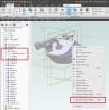
The steps I took to Fully Define Sketch<3> are:-
(Note:- All the dimensions are as the sketch came in your package file).

1) Applied dimensions to Each End Radius.
2) Made sure that both of the "Web" Lines are Parallel to each other, using a Parallel Constraint (They may already LOOK parallel or have been Automatically Constrained, but this makes certain).
3) Dimensioned the width between the two "Web" Lines (Don't worry about their lengths).
4) Constrained the Centre Node of the Larger Radius to Axis<2>, using a Coincident Constraint (This creates a Reference Line that is used next).
5) Constrained the Centre Node of the Smaller Radius to the above Reference Line (or Axis<2>), again using a Coincident Constraint.
6) Made the "Web" Lines Parallel to the above Reference Line (Or Axis<2>), using a Parallel constraint (Again they may already LOOK parallel or have been Automatically Constrained, but this makes certain).
7) Used Tangent Constraint between the Large Radius and Extrusion<4> End Edge.
8) Used Tangent Constraint between the Small Radius and Extrusion<4> End Edge.
9) Finally Centred the "Web" Lines equally over the above Reference Line (Or Axis<2>), using a Symmetric Constraint. At this point, the sketch should be fully Defined,

All of this now ensures that the Pivot Bore and Side Faces are Perpendicular to each other. Previously because your Sketch<3> was slightly "Twisted" in relation to Extrusion<4>(and so in effect also the Pivot Bore Axis), this was not the case.
Now that the Bore and Side Faces are correct in relation to each other e.g. the bore was not "bored on the Piss" (U.K. Technical term ;)), Alibres Constraint Engine is happy.

Hope all this makes sense and helps.

Nick

Edit:- P.S. Note that your Sketch<2> Extrusion<5> is also out of position in relation to Axis<2> (I would move this to after Sketch<3> Extrusion<6>, positioning Sketch<2> with a Concentric Constraint to the Outer Radius).
 
Last edited:

gld

Member
Nick;

Thank you so much for that detailed explanation. It all make perfect sense.

I just assumed (wrong) sketch 2 would be square and perpendicular to the face of the extrusion.
I would never have guessed that i needed that many constraints to make that work.

Still a lot to learn about using constraints.
 

Nick952

Senior Member
Gary,

You are correct to assume that Sketch 2 is square and perpendicular to the extrusion face, as you selected that face to sketch on.
My comment was to point out that Sketch 2 and therefore the Extrude Cut 5 are not centred within (or if you prefer, concentric to) the outer large radius and needed correcting, before moving on with the design.

Looks like an interesting engine, is this your own design?
 
Last edited:

ThomasP

New Member
Hi gld,
I agree with Nick952, that's seems to be a nice little engine.
I had a look at your models and found some unconstrained/undimensioned sketches.
This will increase the risk of models that wont work when you try to change some dimension or assemble them.
When you use the sketcher the element colors will indicate if they are fully constrained, elements become black when fully constrained.
I did some changes to your models trying to constrain the design and make the models more stable.
Have a look and se if there is something you can use.
Regards,
Thomas
 

Attachments

  • Cylinder head assembly - Nick.AD_PKG
    569.4 KB · Views: 9

gld

Member
Gary,

You are correct to assume that Sketch 2 is square and perpendicular to the extrusion face, as you selected that face to sketch on.
My comment was to point out that Sketch 2 and therefore the Extrude Cut 5 are not centred within (or if you prefer, concentric to) the outer large radius and needed correcting, before moving on with the design.

Looks like an interesting engine, is this your own design?

Nick;
No, not my design. Just trying to modify an existing plan, and get more proficient in Alibre.

Thomas;
I need all the help I can get.
Thank you. I'll check it out.
 

gld

Member
Thomas:
Well, I'm back at it. I spent several days trying to figure out how you created constraints 1,2,3. I can only see one of each plane. Explain how to constrain a plane to it self.
 

ThomasP

New Member
Hi Nick,

I didn't constrain it to itself, I constrained the part plane to the assembly plane.
The part and sub-assembly planes are hidden in the assembly I did.
There are several ways of hiding/unhiding reference geometry, one is shown in the attached image.
In the image I have opened the constraint in the design explorer to show the constituents and
right clicked on a line that belongs to the cylinder head and selected "Show Reference Geometry".

Regards,
Thomas
 

Attachments

  • Screenshot assy.png
    Screenshot assy.png
    312 KB · Views: 29

gld

Member
Thanks Thomas

So much to learn in this 3D Cad stuff. I assume now that needs to be done for each part added to an assembly
 

gld

Member
Here we go again. Trying to constrain cam follower roller to the cam face. It will only let me select one section. The roller will not follow the lobe that way. How do I select all sections?
 
Top