What's new

Diameter bolt hole center (bolt circle) pattern for blueprints help

Jason1970

Member
Cannot seem to figure out how to add a diameter bolt hole (B.C.) center pattern. I can add individual center marks to each hole but not the center hole pattern for the bolt circle diameter. I have it on the sketch but when I go to make the print, they disappear. Any suggestions?

Thank you in advance :)!
 

Attachments

  • Alibre model attempt of sample a70 for bp.pdf
    116.5 KB · Views: 11
  • sample a70 for bp.pdf
    135.2 KB · Views: 14

Jason1970

Member
Sure thing, :)
 

Attachments

  • Chap 11 Flange Ring A70.AD_DRW
    423 KB · Views: 4
  • Chap 11 Flange Ring A70.AD_PRT
    632.5 KB · Views: 3

Jason1970

Member
Here is the full pdf of the classroom blueprint original as well.
 

Attachments

  • Full pdf sample a70 for bp.pdf
    253.1 KB · Views: 10

Jason1970

Member
Just making a new print to fix errors on this blueprint in the classroom module. This is one of many I have been redrawing for the class. Thanks for your help :)
 

simonb65

Alibre Super User
I've had a look at your part. What version of Alibre are you using?

To get the reference lines on a drawing you need to create a single hole using the hole tool (not just a circle on a sketch), then circular pattern those holes using the feature pattern tool (not just individual drawn circles in a sketch). The reference lines are then drawn based on the feature that was use to create them as it uses the feature information to determine that they are radially placed holes on a circular pattern.

If you don't use the feature tools, then your only option is to add them to the drawing manually ... which is not the best approach in an application that can automate things like this for you!
 

Jason1970

Member
Using professional currently. I believe I created the singular hole and then used pattern for the 6 hole bottom portion. I did use singular placement for all 4 of the top holes though. If I change the tope holes to pattern will that fix it? Thank you again, your help is very much appreciated :)
 

simonb65

Alibre Super User
I believe I created the singular hole and then used pattern for the 6 hole bottom portion
The design tree suggests you patterned the sketch hole ... not patterned the feature. The former is not the same geometry history and connectivity as the latter. The former only makes copies of the original hole, but has no associated constraints. Using the feature pattern retains these constraints and is what allow the 2D workspace to generate the associated reference lines.

As I said before, this is what you need to do ..
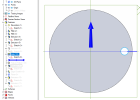
1669996441614.png

1669996477076.png

The drawing now automatically has the reference lines and multiple hole callout (Note: I haven't dimensioned anything or used the same hole as you, this is just for the method) ...
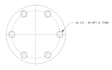
1669996390908.png
 

HaroldL

Alibre Super User
@Jason1970, a point of reference. When you upload a drawing it is preferred that you first create a Package file of it. That will package the drawing and its part together so it can be easily opened by anyone downloading it. The same with assemblies, if you ever need to upload one, so all the components are packaged with the assembly.
 

NateLiquidGravity

Alibre Super User
Jason1970, a point of reference. When you upload a drawing it is preferred that you first create a Package file of it. That will package the drawing and its part together so it can be easily opened by anyone downloading it. The same with assemblies, if you ever need to upload one, so all the components are packaged with the assembly.
Another thing to add to a sticky topic.
 

Jason1970

Member
The patterning from extrude did not change the print to include bolt circle center lines. I saved the file as a package this time. Thank you again for your help, very much appreciated. :)
 

Attachments

  • Chap 11 Flange Ring A70.AD_PKG
    123.8 KB · Views: 4

HaroldL

Alibre Super User
The patterning from extrude did not change the print to include bolt circle center lines.
As @simonb65 pointed out, you need to use the Hole Tool in order to get the center lines to be applied and displayed as needed.
Replace Extrusions 4 & 6 with a Hole tool feature then update and save the model. Then reproject the views to the drawing to see the changes.
 
Top