What's new

Drawings: Hole Callout Issue

jfleming

Alibre Super User
I have noticed this previously, but have never brought it up. The hole callout has some "intelligence" to it, which is indicated by the RED letters in the Dialogue Box.

If you delete one of these red items so that the callout accurately reflects what you need to show on the drawing, that change apparently is only "saved" for the current session only.

Save the drawing.
Close it.
Open the drawing.

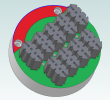
The Hole Callout automatically places this "intelligent" information back into the callout. In my example attached, I want the note to show that there are 18 of these holes. When I opened it back up, it put the 2 back in front of the "18" which I had entered manually. (Note, this is an assembly file, with Qty. 9 items, each with 2 holes (18 total). that is why it wants to show 2, instead of 18.)

Bottom Line... If you aren't paying VERY close attention to everything on the drawing, even if it is something that was not changed, it could easily result in an unclear or incorrect note on the drawing. This seems like a not-so-ideal way for it to operate/function?


Hole Callout.png
 

HaroldL

Alibre Super User
I agree that the hole tool has still some quirks. Like why does it always include the drill point angle? It's not really needed if that is a standard and if something other than 118 degrees is needed then that could be included. There should be a way to set options as to what is included in the call out.

I haven't had a problem with the number of holes for a while, at least in v25.
The call out displays the holes created with the hole tool. Did you create all the holes in one hole tool feature? If you only want to call out two holes maybe changing how they are created. Place the two that you want called out in one hole tool feature and the rest in a separate feature. Then you can just delete the one you don't want. Not exactly the best work flow but may get you a call out that you don't have to keep editing. Until then I'd send this to Support for their suggestions and maybe log for Development.
 

jfleming

Alibre Super User
Thanks for your reply Harold.

The holes in question are within the (9)individual parts that are in the assembly. That is the "root" of the issue.

I am using this assembly file to create a 2D layout drawing for mass producing these punches. Using the Round block as our start point, OP 1 is to create starter holes for our Wire EDM machine. OP 2 is to Tap these holes in question. The block then gets hardened and sent to the EDM where the individual punches are cut out, containing the tapped mounting holes.

I have it modeled as shown below, then just create a 2D flat drawing of the correct orientation. That then gets exported as a .dwg file.
 

Attachments

  • Annotation 2022-08-18 143928.png
    Annotation 2022-08-18 143928.png
    161 KB · Views: 9

HaroldL

Alibre Super User
OK. I see what you're doing. So the 2X holes in only in each piece not the whole assembly which is what you want labeled.

At my old workplace we'd do something similar except that we would only provide programming with one part on the drawing. Programming would then nest as many pieces as needed for the job. But that was sheet metal.


To confirm what you are seeing I just created a test part with two 10-32 holes. I then used that part to create an assembly of nine pieces. On the drawing I inserted the hole call outs and edited it to call for 18X holes. I then saved, closed and opened the drawing. The call out still called for 18X holes. It wasn't until I reprojected the views that the call out updated and added the 2X back in front of the manually entered 18X.

So there must be something auto-updating the call out on your drawing. :confused:

I also noticed that on my drawing the call out has a space between the quantity number and the X (18 X). I thought there was a fix to remove that space so it appeared as 18X but now looks like that space is back in for some reason. I'll have to check with Support on that issue.
 
Top