What's new

fun and games

WJP

Member
Novice here, although I've been designing in 2D for 40 years. I have the Alibre Atom and I am shocked at how much I can draw with the lowest level of the program. I hit the wall a week or so ago at having to put a countersunk hole in a (slightly) conical surface. The part is a 1 1/4" diameter disc with four concentric holes in which 4 flat head screws are used to hold the cap onto the main part. The cap surface is conical as I said (about 5 degrees) and I easily was able to put the 4 holes in for the screws but the 82° c'sink was a challenge for two reasons: 1st was to get the 82° and then to get the right depth to suit the screw head. I saw on the higher dollar version that holes can be called up with threads, counterbores (not sure about countersinks) and such but not so at the Atom level....you pays your money, you gets your choice, understandable but...what do do? So.....I kinda figured out that if I used the fillet tool and called up the half-angle of 41° I could mess around and get a countersunk hole pictorially represented sorta.....but the depth was a challenge (read near impossible) mainly because I don't know how to take distance measurements for 3D object lines. As I said, fun and games....but I'm learning. Of course, if anyone knows how to do this please enlighten me. If I can measure the diameter of the outer edge of the countersink I'm happy. Importing step files from McMaster Carr for screws is a BIG help...if you've never tried it..do!

Thanks all, its been fun :)
 

HaroldL

Alibre Super User
Here's a short demo on measuring the depth of your chamfer.


I went back and reread your post and came to understand that your part has a tapered/conical surface. As such, a regular chamfer won't give a good feature for mating the screw in the hole in an assembly. So I went back and recorded another demo for creating the chamfered hole in a part with the tapered/conical surface. Hope my rambling description helps.

 
Last edited:

WJP

Member
Wow Harold...thanks. You spent considerable effort explaining that! I will watch it again several times. I can see that what I really need to learn is how to be able to draw/sketch in 3D mode and then revolve the shape....I didn't even know that was possible.....I have a long way to go. I am humbled but encouraged, thanks so much.
 

WJP

Member
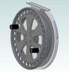
Trying today to follow the second video; Chamfered Hole in Tapered Surface. Not sure how exactly you did it but I created a new sketch on the XY plane with the half profile of the hole with the 5° slope using the project to sketch thing (that's pretty useful!!) and the 41° slope and it finally turned black when I constrained like you did. All good so far, however it would appear that adding the axis in sketch mode is the clincher as it seems to not be available in ATOM. That will have to be ok I guess as I can't expect this simpler version of the program to be as powerful as your version. This is the only part in the whole project that I am unable to draw. The assembly drawing (for pretty) has the 4 cap screws kinda fudged for show. As you said...I can machine it right, I just can't model it right. I can live with that. REVO II ASSY rev1.jpg
 

WJP

Member
Even though I got the half-hole sketch to go black, when I closed the sketch it told me that the sketch was not closed. Oh well...as I can't revolve it without an axis anyway, we will never know :)
All said, I continue to be amazed at how much I can do with this program.

Oh!! I did find the little measure stick icon and did the measurement thing and projected it to the plane or axis...worked great, many thanks for tha too!
 
Last edited:

DavidJ

Administrator
Staff member
Most things are possible in Atom3D, but perhaps not as easily as in Pro or Expert...

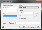
For this case, one method is to cut a simple hole through the part first, then add the chamfer as a separate feature. You can use the first hole face to define the axis for the revolve to cut the chamfer - you don't even need to define an axis.
 
  • Like
Reactions: WJP

HaroldL

Alibre Super User
I couldn't find anything in the Help manual that stated Atom didn't have the axis from sketch.
Here is another method of inserting an axis before the hole sketch. Hope Atom can do this:


I for got to add that the location of the axis defines the hole location. If you need to relocate the hole then just edit the axis (RMB Edit), or open the Equation Editor, and change the offset value of the axis.
 
Last edited:

WJP

Member
Harold: I GOT it :) I was able to insert the axis as you showed in the video, locating it at the same radial distance as I had created my half-hole sketch and so then revolving it worked! Many many thanks. I have a lot to learn but big steps today thanks to you.

DavidJ I will try your method next, but not today!
 

Tapap

Member
Here's a short demo on measuring the depth of your chamfer.


I went back and reread your post and came to understand that your part has a tapered/conical surface. As such, a regular chamfer won't give a good feature for mating the screw in the hole in an assembly. So I went back and recorded another demo for creating the chamfered hole in a part with the tapered/conical surface. Hope my rambling description helps.

these were educational. what mouse are you using? you have amazing control over your model
 

OTE_TheMissile

Alibre Super User
I think in another thread Harold mentioned he was using a 3Dconnexion SpaceMouse. I have one too; it's basically a supplementary device for your offhand that moves in all 6 degrees of freedom. You do all of your selecting with your regular mouse and the SpaceMouse takes control of all of your view manipulation.
 
Top