What's new

Internal gears now available!!

bolsover

Senior Member
Mathematically you should still be able to generate an offset (by the fillet radius) and create the involute for that, then quadratically solve that formula with the diameter formula. It does add more complexity, but as you say someone with a great understanding of the maths would know how!

Is the involute generated from a series of calculated lines then? So can you do some interpolation and approximation to get the points you need? ... or is it a spline?
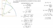
Calculation of the involute is quite simple:
C#:
public static List<Point> InvolutePoints(double baseRadius, double tipRadius, int steps)
        {
            var points = new List<Point>(steps);
            var stepSize = (tipRadius - baseRadius) / steps;

            for (var i = 0; i < steps + 1; i++)
            {
                var step = baseRadius + i * stepSize; // dimension of current step
                var alpha = Math.Acos(baseRadius / step);
                var invAlpha = Math.Tan(alpha) - alpha; // involute function
                var x = step * Math.Cos(invAlpha); // X coordinate
                var y = step * Math.Sin(invAlpha); // Y coordinate
                points.Add(new Point(x, y));
            }

            return points;
        }

The list of X,Y points is used to add a spline to the sketch.

There are a few complexities however..
The root fillet is a simple arc. For some gears, the root fillet arc joins the involute above the base radius. To ensure the end of the root fillet arc and the start of the involute are at the same X,Y location requires interpolation. Taking each point on the involute, I check if this is within a circle from the gear centre to the top of the fillet arc. I keep doing this until a point is found outside the circle. I then create an interpolated point between the last involute point inside and the first outside the circle. This interpolated point is then the first point on the involute.

Here is the code that does the interpolation:
C#:
private int Intersect(Point CirclePos, double CircleRad,
            Point LineStart, Point LineEnd, ref Point Intersection)
        {
            if (IsIntersecting(CirclePos, CircleRad, LineStart, LineEnd))
            {
                //Calculate terms of the linear and quadratic equations
                var m = (LineEnd.Y - LineStart.Y) / (LineEnd.X - LineStart.X);
                var d = LineStart.Y - m * LineStart.X;
                var a = 1 + m * m;
                var b = 2 * (m * d - m * CirclePos.Y - CirclePos.X);
                var c = CirclePos.X * CirclePos.X + d * d + CirclePos.Y * CirclePos.Y -
                        CircleRad * CircleRad - 2 * d * CirclePos.Y;
                // solve quadratic equation
                var sqRtTerm = Math.Sqrt(b * b - 4 * a * c);
                var x = (-b + sqRtTerm) / (2 * a);
                // make sure we have the correct root for our line segment
                if (x < Math.Min(LineStart.X, LineEnd.X) ||
                    x > Math.Max(LineStart.X, LineEnd.X))
                {
                    x = (-b - sqRtTerm) / (2 * a);
                }

                //solve for the y-component
                var y = m * x + d;
                // Intersection Calculated
                Intersection = new Point(x, y);
                return 0;
            }

            // Line segment does not intersect at one point.  It is either
            // fully outside, fully inside, intersects at two points, is
            // tangential to, or one or more points is exactly on the
            // circle radius.
            Intersection = new Point(0, 0);
            return -1;
        }

David
 

albie0803

Alibre Super User
I'm really interested in modelling gears for 3D printing where a radius tip is quite natural.
Do you employ any sort of tip relief to prevent chipping of the tooth?
David
To answer your question, normally only ground gears are the ones that may have tip relief ground into them, and its normally a tightening of the involute on the outer section of the tooth rather than a radius on the tip. The vast majority of the gears we do have none.
 
Our shop has fully dived into cutting involute splines in the last year. Being a CMM programmer I have been working to get my head wrapped around the intricacies of the entire process. We use Quindos with a gear add-on to check the final dimensions.

I hope I don't muddy the waters but here are my thoughts based on my limited understanding.

Line A-C would always need to be tangent to the base diameter, but the angle of that line relative to the original pressure angle at the pitch diameter would need to change to pass through the center of the fillet as it changed. The distance from the tangency point of A-C at the base diameter to the pitch diameter intersection can be calculated TAN(PRESSURE ANGLE*BASE/2). That is also the pitch diameter/2. As the fillet size changes, the angle of A-C relative to the original pressure angle changes in order to retain the tangency to the base diameter. I think the trick is that C is equal to the original length from the base dia tangent point to the pitch diameter intersection, plus or minus the arc length (360/ (BASE DIA Pi R SQ)* the angle change at the base diameter between the original 20° pressure angle and what ever angle is produced from A-C passing thru the center of the fillet. ...I think.

Regardless, I think line A-C would always remain tangent to the base diameter. Wouldn't it?

Brad
 

bolsover

Senior Member
Our shop has fully dived into cutting involute splines in the last year. Being a CMM programmer I have been working to get my head wrapped around the intricacies of the entire process. We use Quindos with a gear add-on to check the final dimensions.

I hope I don't muddy the waters but here are my thoughts based on my limited understanding.

Line A-C would always need to be tangent to the base diameter, but the angle of that line relative to the original pressure angle at the pitch diameter would need to change to pass through the center of the fillet as it changed. The distance from the tangency point of A-C at the base diameter to the pitch diameter intersection can be calculated TAN(PRESSURE ANGLE*BASE/2). That is also the pitch diameter/2. As the fillet size changes, the angle of A-C relative to the original pressure angle changes in order to retain the tangency to the base diameter. I think the trick is that C is equal to the original length from the base dia tangent point to the pitch diameter intersection, plus or minus the arc length (360/ (BASE DIA Pi R SQ)* the angle change at the base diameter between the original 20° pressure angle and what ever angle is produced from A-C passing thru the center of the fillet. ...I think.

Regardless, I think line A-C would always remain tangent to the base diameter. Wouldn't it?

Brad

Particular thanks to @BradMorris64 for pointing out that line A-C would be tangent to the base diameter.
This observation has led me to a solution. I still need to finalise the current very rough code but I do now know how to solve the problem reliably.

Going back to an earlier sketch..
The problem was to calculate the positions of Points A, B and C where:
A is the centre of the tip radius circle.
B is the tangent point of the tip radius circle and the tooth tip (addendum) diameter
C is the tangent point of the tip radius circle and the tooth face.

TipRadius.png

As a starting point, note that the line A-C is tangent to the gear base circle (it's fundamental to the involute curve).

The diameter of the base circle is given as db = dp Cos(alpha)
Where:
db is the base circle diameter
dp is the gear reference diameter (for a module 1, 18 tooth gear this is 18mm)
alpha is the pressure angle in radians

Below is a sketch of a full tooth (Module 1, teeth 10)
This sketch shows the line C-A extended to point P tangent to the base circle.
TipRadius3.png

From the above, we can see the right angle triangle OPA.
The dimensions O-P and O-A are known. It is a simple matter to calculate the length P-A using Pythagoras.
O-P is the base radius, O-P is the tip (addendum) radius minus the radius of the tip radius circle.
With the dimensions P-A and A-C (tip radius circle) known it is again simple to calculate the length O-C using Pythagoras.

Here is the code to calculate O-C for any given base radius, addendum radius and fillet radius:
C#:
public static double CentreToTipReliefRadiusStart(double baseRadius, double addendumRadius, double reliefRadius)
        {
            var oa = addendumRadius - reliefRadius;
            var oaSquared = oa * oa;
            var opSquared = baseRadius * baseRadius;
            var paSquared = oaSquared - opSquared;
            var pa = Math.Sqrt(paSquared);
            var pc = pa + reliefRadius;
            var pcSquared = pc * pc;
            var ocSquared = pcSquared + opSquared;
            return Math.Sqrt(ocSquared);
            
        }

With O-C now known it is possible to calculate the position of point C on the involute curve

Here is the code to calculate the X,Y point C.

C#:
public static Point PointOnInvolute(double baseRadius, double distanceToInvolute)
        {

                var alpha = Math.Acos(baseRadius / distanceToInvolute);
                var invAlpha = Math.Tan(alpha) - alpha; // involute function
                var x = distanceToInvolute * Math.Cos(invAlpha); // X coordinate
                var y = distanceToInvolute * Math.Sin(invAlpha); // Y coordinate
                return  new Point(x, y);
 
        }

With the location of Point C now available it is time to calculate the location of Point A.
There are a few ways this can be done but I chose to calculate the angle from the horizontal plane to line O-A
This is the sum of the included angle from the horizontal to O-C and the included angle C-O-A.
All the dimensions of these triangles are known and the angles can be calculated using the cosine rule.

Code for the calculations below:

C#:
 public static double CosineRuleAngle(double sidea, double sideb, double sidec)
        {
            var a = sidea * sidea;
            var b = sideb * sideb;
            var c = sidec * sidec;
            
            return Point.Degrees(Math.Acos((b + c -a)/(2 * sideb * sidec))); // Point.Degrees just converts the result from radians to degrees.
        }

So now, we know the distance and angle (from horizontal) to point A.
A few more simple calculations and the point can be added to the sketch.

To do: calculate the position of point B (should be simple)
Reflect points A, B, C about the tooth centreline
Trim the involute curve to length.
Trim the Addendum Arc to length.

Finally add the tip radius arc.

Below is what I have at present - all automatically calculated and sketched.

TipRadius4.png

Thanks to all for their input.

David
 
This makes me very happy that I was able to help in anyway! It took me a long time to get my head wrapped around even the basics of involute splines. My understanding is still very rudimentary.

Continued success with your project!

Brad
 

bolsover

Senior Member
This makes me very happy that I was able to help in anyway! It took me a long time to get my head wrapped around even the basics of involute splines. My understanding is still very rudimentary.

Continued success with your project!

Brad
Thanks Brad..
All working as I want now.
I just automatically generated the profile shown below.
I have a big code tidy up to do now. To clean up all the test code and remove a whole bunch of near duplicated code.
The Tip relief radius and the Root relief radius are both variables that can be adjusted as needed but I'll probably set some default values.

The Root relief is currently just another arc. In the fullness of time I intend to replace this with a 'correct' trochoidal curve so gears with fewer than 18 teeth will be constructed with appropriate undercutting. The math for this is challenging though!

David

TipRadius5.png
 

bolsover

Senior Member
Getting ready for an update..

I've added basic support for generation of internal gears:
Screenshot 2022-10-04 144004.png

I have a few things to do before it will be ready for an initial release but thought I'd share the progress..
Gears in the attached test package were generated using the utility.
Things to note:
1 No relief radius in inner gear - root or addendum.
2 Not yet tested generation of helical internal gears
3 Contact ratio is not being calculated.
4 Only the wheel can be defined as internal
5 Not yet checking to ensure wheel is bigger than pinion

I hope to have an initial demo add-on ready in the next few days.

David
 

Attachments

  • TestAssy.AD_PKG
    415.5 KB · Views: 2

JimSim

New Member
A "topping" hob does cut a tip curve. The curve is a trochoid generated by the cutter. The only real way to generate the root and tip is the model the hob and generate the profile from that. Albie0803 is correct that non-topping hobs leave a sharp corner. Typically the will be broken with a chamfer after hobbing so that handling damage (dents on the OD) does not affect the contact profile. Also the burr ridge left fron hobbing can leave a nasty laceration.

The profile (contact face) is an involute as others noted. An involute can be generated by unwinding the circumference of the base circle.
 

Attachments

  • Screenshot 2022-10-05 101542.jpg
    Screenshot 2022-10-05 101542.jpg
    159.5 KB · Views: 31

bolsover

Senior Member
A "topping" hob does cut a tip curve. The curve is a trochoid generated by the cutter. The only real way to generate the root and tip is the model the hob and generate the profile from that. Albie0803 is correct that non-topping hobs leave a sharp corner. Typically the will be broken with a chamfer after hobbing so that handling damage (dents on the OD) does not affect the contact profile. Also the burr ridge left fron hobbing can leave a nasty laceration.

The profile (contact face) is an involute as others noted. An involute can be generated by unwinding the circumference of the base circle.
@JimSim
Thanks for the input. The tooth face for the gears is generated as an involute curve. Alibre does not support parametric curves, so I calculate a series of 25 X, Y points on the curve and then apply a spline to fit. The gear root is a simple arc as is the tip relief, but the radii of these curves can be adjusted as required. I would like to use trochoid curves for the root and generate this with the appropriate undercutting. I have some information as to how these are computed but have not yet attempted to implement.

If you have any references for the trochoid curve I'd be very interested.

David
 

JimSim

New Member
@JimSim
Thanks for the input. The tooth face for the gears is generated as an involute curve. Alibre does not support parametric curves, so I calculate a series of 25 X, Y points on the curve and then apply a spline to fit. The gear root is a simple arc as is the tip relief, but the radii of these curves can be adjusted as required. I would like to use trochoid curves for the root and generate this with the appropriate undercutting. I have some information as to how these are computed but have not yet attempted to implement.

If you have any references for the trochoid curve I'd be very interested.

David
I was doing a lot of special gears. I needed exact detail to calculate gear strength.

The root becomes very important in lower numbers of teeth. The hob cuts out the root on the side opposite the profile it is cutting. They turn into an ace of spades. I don't have the formulas. I would take the hob and index it. Then connect the points with a spline. Very manual. Google hob cutting pattern and you will see images. There are companies that make software to do it. But for my small company can't afford it.
 

Attachments

  • IMG-4772.jpg
    IMG-4772.jpg
    1.7 MB · Views: 10

bolsover

Senior Member
Hi Bolsover,
Maybe this could help you:

@GIOV Thanks for the link. I have tried a couple of trochoid generation routines. The tricky part is not so much the trochoid but knowing where it should start and end in relation to the involute and base circle.
I'm just working each problem in turn. My present aim is to generate internal and external gears both straight and helical with simple radii at root and tip. This should enable reasonable accuracy for any gear above 18 teeth.
David
 

bolsover

Senior Member
Bolsover,
Certainly it is not ease task.
Here is a dialog about, I think, you task where explain the "trochoidal fillet".

@GIOV
Thank you so much for that link! I have seen a couple of similar explanations of the undercut but none as clear as this. I'll start by getting the formulae working in Excel before attempting to code in C#.
I'll probably tackle this after a prototype internal gear solution.
Thanks, David
 

bolsover

Senior Member
Bolsover,
Certainly it is not ease task.
Here is a dialog about, I think, you task where explain the "trochoidal fillet".

Quite a hack but just generated this m1,z8 gear with trochoidal undercut.
Not certain the gear is correct but the trochoidal curves look good.

z8withtrochoidalundercut.png
A few test curves generated using the formulae in article.
curves.png
 

bolsover

Senior Member
I finally got round to fixing a couple of issues that prevented the Internal gear generation from working as smoothly as I wanted. - So a new release is now available.

Version 1.3.0.0

It is a long way from perfect but certainly usable for both internal and external straight cut and helical gears.

I will need to do some major revisions to the code base to address some of the shortcomings (like undercutting of gears with fewer than 17 teeth).

Feedback and constructive criticisms always welcome.

David
 
Top