What's new

How to create a parting line for a non-symmetry part to make the core and cavity of the injection mold by Alibre feature?

Suppakit

Member
Hi everyone,

I have a challenge from my customer for use Alibre to make the mold base for a non-symmetry part by using the "parting line" to define which is core or cavity.
I have tried the Boolean method but it has worked for only symmetry or single planar, My customers almost use Solidworks and NX that have already parting line tools or that's mean
there are many tools for "creating 3D surfaces from sketch or 3D sketch, and I need more suggestions for how to solve it..

Thank you in advance,
Suppakit.
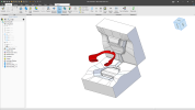
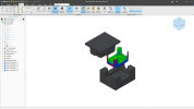
1683095133617.png
 
Correct me if I'm wrong but the model in the screenshot looks like it was created in Solidworks. I wasn't very fond of their parting line tools, they created too much unnecessary geometry, planer geometry could contain extra faces for no added benefit. The last time I used them was in version 2015.
 

Suppakit

Member
Correct me if I'm wrong but the model in the screenshot looks like it was created in Solidworks. I wasn't very fond of their parting line tools, they created too much unnecessary geometry, planer geometry could contain extra faces for no added benefit. The last time I used them was in version 2015.
Hi @multicaduser
Thank you for your suggestion, I forgot to attach file, Have you ever tried to make the parting line for any injection mold such as the chair or kind something similar?
1683180320410.png
 

Attachments

  • Wear mask mold.AD_PKG
    3.7 MB · Views: 6
  • Plastic chair mold design.AD_PKG
    1.5 MB · Views: 4
Of the two, the mouth guard mold is the more interesting to me. Right now I don't see a way to model it in AD without something like horizon/isocline curves. That type of function would be the only way to determine the parting line. It might be possible to add the option to the 3d sketch function which now only seems to be able to add face edges.

I'm going to see how difficult the chair mold cavity would be to model, I have a vague idea on how but will see how good my imagination is. Thank you for the opportunity.
 

NateLiquidGravity

Alibre Super User
I have an idea but have not tried it.
1) Create a 2d sketch of the parting line with minimal offset added to create a sketch loop.
2) Use a wrap feature to create a minimal thickness around the part at the parting line.
3) Go back and adjust your 2d parting line sketch as needed.
4) Convert the outer wrap faces to surface.
5) Thicken surface beyond the distance the mold will be.
6) Convert the top faces of that to a surface.
7) Use that surface to split the mold.

Just a guess though...
 
Very similar to what I was thinking for the split surface, however how to approximate the silhouette of a curved surface is the issue for the mouth guard part. I did a quick look into wrap after reading the mention in your post but have never used it before, thanks for the suggestion.
 
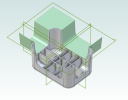
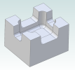
Ok, making a trim surface for the chair looks like it will work though I haven't gone full bore yet and tried to split it out (see image).
1683229165932.png
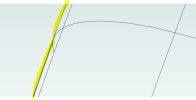
However, getting parting curves on the mouth guard is still kicking my butt. The software can create visual representation of the horizon curve which would be exactly what is needed to create the actual parting. The yellow highlight in the image below is the visual horizon. Going to keep banging away at it but right now thinking a different piece of software to create the trim sheet.

1683229312691.png
 
If Solidworks is out of your budget, this is a case where Plasticity would work really well. It can handle multiple bodies and sheets in context and you should be able to import your solids/sheets back to Alibre for further work. The main reason for me would be ease of use and strong booleans. Something I need to try some day. The route you're attempting manually is what I would try though.
 
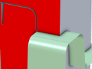
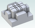
So I created the sheet body that would trim the chair starting at the edge of the chair and extending out past the side of the block. The boolean subtract and the sheet were created from the same source and the edges match exactly (see image below). The sheet body was imported using "insert surface" then "trim model" was tried but it didn't trim off the rest of the block. There are more things to try but I'd like to know if "trim model" doesn't work this way. One thing I'd like to add is the image uses a precise section for clarity, that is not the complete model.

tia

1683315562214.png
 
This time a core surface file was created by deleting all the cavity faces from the chair part and exporting an iges file of the remaining. The the iges files was inserted into the file and stitched to the parting surface then used to trim the solid. It works but is not preferred. Is this close to the right way or is there a better?

1683317736625.png
 
Model Engineer, you might like this video.


While Plasticity looks very interesting there is a difference between modeling which creates geometry and designing which has intent. I hope the engineer succeeds, it looks like he is putting a substantial amount of effort into the software.
 
It is an option if you have already completed your design in Alibre. Plasticity is meant for artists, not engineers. It is doing well for its intended audience. The parasolid kernel allows it to do operations Alibre can't do (and isn't try to do) such as advanced surfacing and synchronous modeling. The Rhino workflow of keeping construction geo in hidden layers for later use can be a turn off for many, but if there are only 2 or 3 steps involved after the design is completed, it is certainly manageable.
I'm still curious about your workflow in Alibre, as it is always nice to have workarounds that sit tight in a single piece of software.
 
Morning Model Engineer. I'll try creating a pkg file, haven't done it before and have no idea what is involved but I'll look it up. I'm not sure if I like the workflow as it is not completely parameterized, which has limitations. I agree that keeping the design in a single piece of software has many advantages, and the reason for posting the youtube video was for education, which is always good.

As my tag says I've used many cad systems, for over 40 years to be honest. I have several personal laws in modeling, such as starting over may be the best course, and it's sister law if what you are doing isn't working try something else. I haven't had a chance to do much testing in AD and am in the process of finding out which workflows work and which don't. I want to try at least one more workflow before posting anything to see if these other ideas have any advantages.

I like getting my ideas challenged, it just makes for a better modeler. Thank you for your reply.
 
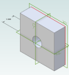
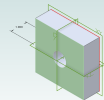
So regarding my post of Friday at 2:39 pm, I was wondering why that didn't trim, it just gave an error in the part tree with no message. To test the workflow I created a new file that had a simple block with a hole extruded at 1".
1683494983815.png
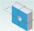
Then I created a surface from face at the 1" side.
1683495044421.png
Then did a move face on the 1" side.
1683495129282.png
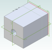
So far so good, a trim model trim model was done with the created surface and bingo, the solid was trimmed.
1683495235642.png
This is the same geometry style that failed in trying to trim the chair, now I have to figure out the differences. One inconvenience is the created surface is not parametric to the original 1" extrude and does not update if the distance is changed. This is minor as long as it's understood.

Minor as it is I did attach the package file of the trim experiment.

Going back to the chair, is there a tolerance that can be loosened to help the trim succeed? I found nothing on modeling tolerances but if there is a kryptonite for me it's research.

Thanks to all who have replied.
 

Attachments

  • solid_trim_experiment.AD_PKG
    27.2 KB · Views: 0

NateLiquidGravity

Alibre Super User
The other model design is definitely possible but much, much harder to do "right" in Alibre Design. If those kinda things are your business - frankly; I'd look at something other than Alibre Design.
 
Thank you NateLiqGrav, interesting thought. There are many things to like about AD, too many to just dismiss it. One thing to take exception with is the "do it right" comment. The chair core was modeled several different ways in less that a couple of hours with virtually no AD experience. There are advantages and disadvantages to the methods, but in the end the result is the same. I am self taught on every cad system I've ever used, which over 40 years is quite a few. Not to get preachy here but I don't give up when something is hard and I try not to blame the hammer for a bent nail.

If you don't mind my asking a couple of questions, for perspective, what kinds of things do you model and what features would you like to see AD include?
 

NateLiquidGravity

Alibre Super User
Don't get me wrong - I love Alibre Design.

I was talking specifically about this model. That is a very specialized thing that I doubt Alibre will implement. If the Solidworks mold parting tool creates this mold split in minutes you could save a business lots of money in the long run.
index.php


As far as what I think Alibre should implement... That is a big list but most of it is basic sketch and drawing things or fixing things for better project management (like package files but way better).
 
Wouldn't want the SW style parting implemented. Yes, self taught in SW too, and the automatic parting line tools are not that good, in my opinion, and they create parting lines that are complicated and difficult to build, like the mouth guard example.

More curve creation options, especially in 3d sketcher. would greatly improve AD capabilities.

One of the greatest capabilities for me in AD is configurations. Flexible components speed up design greatly and minimize the number of components needed in a library. Done without care configurations can actually hinder the process. I've seen SW files with configurations that were horrendous large spreadsheets with so much duplication in entries that they were large slow files. I really like the ability to have configurations in the global parameter file, this is exciting and it will be interesting to find those limitations.

It would also be interesting to see save as include adding a prefix or suffix to all files or maybe even string replacement.
 
Top