What's new

How would you approach this Torus Coil in Alibre?

DBC

Senior Member
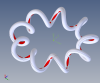
I saw this torus coil on Instagram and thought it looked cool and thought I would give it a whirl. I can think of a couple ways to get the initial coil in TurboCAD (sweep with a twist, bend a straight helix sweep) but getting the extended straight pieces has me stumped there. I tried in Alibre and can't even figure out how to get the initial curved helix. I still have access to SoildWorks so I tried it there and was able to figure it out by surface sweeping a line with a twist around a circle. then selecting the outer edges of the swept object and projecting that to a new sketch. From there it was just a matter of adding some lines and a circle to sweep the final path. It was pretty easy in SW because of the tangent constraints they have. Sorry a bit difficult to explain. Hopefully one of you fellows has some ideas how to do it in Alibre.

Attachment 1 is the Instagram one I saw.
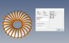
Attachment 2 is my result made in SW, opened in AD and rendered in KeyShot.

EDIT:
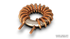
Attachment 3 is my result from TurboCAD. Very difficult to get the tangent bent corner that eventually projects forward. I am not happy about the tight bends.
 

Attachments

  • Screen-0000.jpg
    Screen-0000.jpg
    52.1 KB · Views: 39
  • Torus Coil (SW-AD-KS) DBC_1200.png
    Torus Coil (SW-AD-KS) DBC_1200.png
    430.9 KB · Views: 41
  • Torus Coli (TC-LW) DBC_1200.png
    Torus Coli (TC-LW) DBC_1200.png
    470.8 KB · Views: 32
Last edited:

HaroldL

Alibre Super User
That script has been around for a while now. I think Max wrote it so maybe he can give a pointer or two. I've only "played" with it a couple of times and haven't had time or need to use it for anything - yet.
 

anson

Member
This is how I do it. Sort of crude, but works for me.
 

Attachments

  • toridial transformer.AD_PKG
    2.5 MB · Views: 30

DBC

Senior Member
Hand made.

Thanks George. Sadly, I have noticed that this method leaves a very noticeable seam at all the junctions. I do appreciate both yours and Anson's efforts.
 

Attachments

  • Screen-0002.jpg
    Screen-0002.jpg
    38.1 KB · Views: 30

HaroldL

Alibre Super User
Don,
In order to get a toroidal coil it will need to be created as a sweep with a 3D sketch as the path. Unfortunately the 3D spline lacks the controls to produce a curve path that has continuous curvature. It ends up with a square shape.

This is definitely a 3D path that begs for a script to be written for it. So, if anyone has an itch to create one or maybe modify the "Everyone Loves a Slinky" script so it can create this shape, that would be helpful.
I started to create one manually and it is tedious. Here are some images, and the part file, of what I was able to create in about 30 minutes.

My workflow goes like this:
  1. Create a new angled plane. (Angle = A1)
  2. Create a 2D sketch and Project to Sketch (reference and maintain association) the 2D circular sketch that coincides with the next point.
  3. Insert Point from Sketch and apply to the point created from the PtoS operation.
  4. Exit the sketch.
  5. Create the next plane and repeat.
Once I had these few planes, sketches and points defined, I created a 3D sketch spline coincident to all the points and created the Sweep you see.

toroirdalStart_ISO.png

toroirdalStart.png

toroirdalStart_TV.png
 

Attachments

  • toroirdalStart.AD_PRT
    661 KB · Views: 6
  • Like
Reactions: DBC

DBC

Senior Member
Don,
In order to get a toroidal coil it will need to be created as a sweep with a 3D sketch as the path. Unfortunately the 3D spline lacks the controls to produce a curve path that has continuous curvature. It ends up with a square shape.

This is definitely a 3D path that begs for a script to be written for it. So, if anyone has an itch to create one or maybe modify the "Everyone Loves a Slinky" script so it can create this shape, that would be helpful.
I started to create one manually and it is tedious. Here are some images, and the part file, of what I was able to create in about 30 minutes.

My workflow goes like this:
  1. Create a new angled plane. (Angle = A1)
  2. Create a 2D sketch and Project to Sketch (reference and maintain association) the 2D circular sketch that coincides with the next point.
  3. Insert Point from Sketch and apply to the point created from the PtoS operation.
  4. Exit the sketch.
  5. Create the next plane and repeat.
Once I had these few planes, sketches and points defined, I created a 3D sketch spline coincident to all the points and created the Sweep you see.

View attachment 28976

View attachment 28974

View attachment 28975

Thanks Harold. Hopefully someone will take that scripting on. Thanks for taking time to give it a whirl.
 

HaroldL

Alibre Super User
Stefan,
You work fast!
Maybe you could help decipher what the Scale values are/do. I've tried several variations of the "Everyone Loves a Slinky" and cannot make sense of what those inputs control - other than locking up Alibre if I enter something that will not compute. If instead of Loop Scale, Height Scale and Major Helix Width Scale it would accept inches or millimeters or whatever units the model is in.
 

idslk

Alibre Super User
Hello Harold,
well it took me less than 30 min. from reading to posting...i had to hurry, wife was waiting with dinner ;-)
Maybe you could help decipher what the Scale values are/do.
I'll try:
The Turn density represents a value of how many wraps will be done. Greater values will make the coil wraps tighter, but too much and the "helix" will intersect itself...
The Major Helix Width Scale is a value which is calculated with a cosine and starts at a "radius" of "x"-model units.
The Loop Scale is the diameter of a wrap of the coil, also given in medel units
HeightScale was used in the original slinky to give the slinky a "length". As far as the coil is on the same plane/level the "length" is not needed.
The Angle increment is used for the accuracy of the wraps.
The wire diameter should speak for itself and is also in model units ;-)
So if you use the prefilled values and you edit the path sketch, you should be able to measure the distance between the start point of the helix and the z-axis. It should show as Loop Scale + Width Scale in model units = 1 + 2 = 3 (for me mm, for you maybe inch)
Regards
Stefan
Hello Don,
Thanks for taking the time to do this.
It was a pleasure for me.
Regards
Stefan
 

bigseb

Alibre Super User
Don,
In order to get a toroidal coil it will need to be created as a sweep with a 3D sketch as the path. Unfortunately the 3D spline lacks the controls to produce a curve path that has continuous curvature. It ends up with a square shape.
It is possible to do this. If the spline is continuous then it will remain smooth. See attached.
Then its simply a case to trim the model so the cut is perpendicular to the spline and use tangent loft to create the runouts. I lost interest before I could finish but you get the idea.
 

Attachments

  • FrankEatsBeans.AD_PRT
    2.4 MB · Views: 15

HaroldL

Alibre Super User
If the spline is continuous then it will remain smooth.
The sweep may be smooth but the curvature is not continuous. I swapped out your Revolve Boss for a Revolve Cut and, as you can see, there is a lot of irregular cuts where the toroidal coil was cut because of this irregularity.

That's just something that will have to be "accepted" until Alibre refines the 3D spline with more controls. It also depends a lot on just how accurate you want the model to be when using the 3D spline. In the examples we've been working with there are only four points per coil. I suspect (and will have to try this) that if there were eight points per coil the curvature would be more accurate.

BTW, I like your use of sketches to create the path points. It looks a bit faster and easier than the method I used in my example.
 

Attachments

  • FrankEatsBeansNonCircularToroidalCoil.png
    FrankEatsBeansNonCircularToroidalCoil.png
    269.3 KB · Views: 20

bigseb

Alibre Super User
The sweep may be smooth but the curvature is not continuous. I swapped out your Revolve Boss for a Revolve Cut and, as you can see, there is a lot of irregular cuts where the toroidal coil was cut because of this irregularity.

That's just something that will have to be "accepted" until Alibre refines the 3D spline with more controls. It also depends a lot on just how accurate you want the model to be when using the 3D spline. In the examples we've been working with there are only four points per coil. I suspect (and will have to try this) that if there were eight points per coil the curvature would be more accurate.

BTW, I like your use of sketches to create the path points. It looks a bit faster and easier than the method I used in my example.
Yeah AD really isn't the best tool for this. Best way (for me at least) is to use the flow tool in Moi. AD is just too basic for this sort of thing.
 
  • Like
Reactions: DBC

HaroldL

Alibre Super User
So if you use the prefilled values and you edit the path sketch, you should be able to measure the distance between the start point of the helix and the z-axis. It should show as Loop Scale + Width Scale in model units = 1 + 2 = 3 (for me mm, for you maybe inch)
Regards
Stefan
Thanks for the explanation. I think the word "Scale' appended to the parameter names is confusing me.
Even with my system settings set to Decimal Inch the part is created in mm size. I was expecting it to measure 3 inches if it's in model units. Is there a switch for that?
 

Attachments

  • ToroidCoilSize.png
    ToroidCoilSize.png
    146.6 KB · Views: 23
Top