What's new

Introducing Myself

Neil Wyatt

Member
Hi all,

I'm Neil Wyatt, editor of Model Engineers' Workshop magazine.

We're going to run a tutorial series for Atom3D with support from Alibre and Mintronics.

As part of this I'm finding my own way around Atom3D, moving across from TurboCAD Deluxe. After a bit of a slow start, I'm getting the hang of it making parts now, but still to do an assembly.

Here's a question to get started on. I can import a DXF as a 2D drawing, but is there a way to display a dxf (or just an ordinary jpg) in the part creation window? I base a lot of my models on things like undimensioned drawings, photos or even woodcuts, so having an image on a plane to use as a reference would be really useful.
 
Hi Neil -- The thing about "importing" 2D Geometry is that it can be painful to learn. Whenever possible, import only that geometry you will need for a specific Sketch (something that will take you some time to learn). It will Load into the Drawing editor. You will need to "activate the "Sketch" in the Drawing Editor performa a (CtrlA) select all and Copy the selected geometry to be able to Paste it into a Part Sketch (where you will need to Constrain and Dimension it) to effectively use it.

Does this make sense to you?
 

GIOV

Alibre Super User
Hi Neil,
ACAD Drawing is feasible throughout 2D Drawing WorkSpace:

1. - Make the ACAD drawing;

2. - Save as a dwg or DXF;

3.-Open Alibre Atom3D the 2D Drawing WorkSpace;

4.-Open the Dwg/DXF;

5.-Edit and Copy;

6.-Open The Part and active the 2D View into the Plane that you like start the Sketch;

7. - Paste the Drawing;

8.-Some time in 2D WorkSpace need to clinic the drawing for to avoid confusion with hidden object.

I hope this help!
Open a Blank Sheet.JPG Open the Dwg.JPG
Active the Sketch.JPGSelect the Drawing that you like to copy.JPG
Paste the drawing into the Part WorkSpace in the 2D Plane actived.JPG And Sart to do the part with Features.JPG
Open a Blank Sheet.JPG Open the Dwg.JPG
Active the Sketch.JPG Select the Drawing that you like to copy.JPG
Paste the drawing into the Part WorkSpace in the 2D Plane actived.JPG And Sart to do the part with Features.JPG

Here is a model that I made when was a child. She sails very well!

Giovanni's boat #1.jpg
Vanguard 1844
Congrats for your Steam Machine!
 

MilesH

Alibre Super User
Just to add that you can open or insert a jpg in Drawing workspace, where you can Scale it. Draw a line across a known dimension on the image and then Scale by the ratio of the line dimension to the actual dimension. Scaling is relative to the centre point of the image. Now you can "trace" over the image and then Copy and Paste into a Sketch in Part workspace.
 

Neil Wyatt

Member
Thanks folks,

My problem was that pasting didn't appear to work - I had to zoom out.

Now I have my example gear in a sketch I can extrude it fine, scale and move it, but I'm struggling to dimension it or apply a constraint to it. The dimension and constraint tools pick up on my reference lines but ignore the gear outline.

It appears to be being treated as a 'symbol' so I assumed 'explode symbol' would convert it to editable lines (this works with text), but this doesn't seem to work.


upload_2018-10-3_11-21-3.png
 

Attachments

  • upload_2018-10-3_10-55-16.png
    upload_2018-10-3_10-55-16.png
    150.1 KB · Views: 7
  • upload_2018-10-3_11-10-5.png
    upload_2018-10-3_11-10-5.png
    153.4 KB · Views: 6

Neil Wyatt

Member
P.S. I get the scaling a jpg and I like the galleon, but for some reason my quotes were activating a 'spam like' filter!
 

DavidJ

Administrator
Staff member
Neil - try doing the explode step in the 2D drawing workspace before copy/pasting across to part sketch workspace. With some symbols you may have to perform several explodes (until you no longer see the symbol icon when hovering over the figure.
 

Neil Wyatt

Member
Neil - try doing the explode step in the 2D drawing workspace before copy/pasting across to part sketch workspace. With some symbols you may have to perform several explodes (until you no longer see the symbol icon when hovering over the figure.

Great! that's worked. Of course my object is so complex it isn't practical to dimension! Clearly some care needed to use the right procedures with the right parts.
 

DavidJ

Administrator
Staff member
That is why we often say it can be simpler in the end to re-draw. Imported DXF can be very complex - I recommend users to design using multiple very simple features to build up a part. That makes defining each one easier, and also makes subsequent edits easier too.

Sketch constraints can often be more efficient than applying dimensions as you build up a complex part (you can constrain to previous features).
 

Neil Wyatt

Member
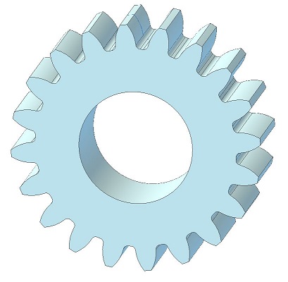
I realised later that the best answer would be to isolate one tooth of the gear, it can then be 'fixed' and duplicated.
 
I realised later that the best answer would be to isolate one tooth of the gear, it can then be 'fixed' and duplicated.

The attached part has an involute gear tooth modelled then duplicated into a circle to create a gear. The module and tooth count etc can be edited in the part EquationEditor to make change as required.

I am told by some finikky types lurking here that the gear is close but not perfect to be a "true" involute gear ... but it is very close.

SpurGear_03.jpg
 

Attachments

  • SpurGear.AD_PRT
    1 MB · Views: 9

Neil Wyatt

Member
Neil -- Why not use the AlibreScript routines to generate a SpurGear?

Probably because I haven't discovered Alibrescript yet! :)

I've figured out that I can use equations to control dimensions, but my problem at the moment is running before I can walk. I'm currently playing with lofting and discovering things like how the final result of series of lofts and cuts depends on the order they are in.
 

Neil Wyatt

Member
The attached part has an involute gear tooth modelled then duplicated into a circle to create a gear. The module and tooth count etc can be edited in the part EquationEditor to make change as required.

It seems the configuration element isn't supported in Atom3D.

I think it should be possible to do something similar though, once I get my brain around it. Approximations are fine - there are plenty of ways to approximate an involute that's well inside normal machining tolerances.
 

Specktech

Member
Hi Neil -- The thing about "importing" 2D Geometry is that it can be painful to learn. Whenever possible, import only that geometry you will need for a specific Sketch (something that will take you some time to learn). It will Load into the Drawing editor. You will need to "activate the "Sketch" in the Drawing Editor performa a (CtrlA) select all and Copy the selected geometry to be able to Paste it into a Part Sketch (where you will need to Constrain and Dimension it) to effectively use it.

Does this make sense to you?
I am trying to get some really simple 2d drawing's into Alibre Atom 3d. Using Turbocad 2019 Deluxe. I can save my file as a DWG. It loads my drawing into the Drawing editor just fine. But I can't seem to get it into a part sketch? I followed these steps using, activate, CtrlA, CtrlC, CtrlV. But it does not seem to work. Any ideas what step I am missing or doing wrong? My goal is to use T.C. to draw up these simple drawings, send them over to Alibre. Then set them up into a loft. And create a 3d part.
 

HaroldL

Alibre Super User
The first steps sound right. Are you starting a sketch on a plane in Atom 3D when you Ctrl V to paste the copied sketch into Atom 3D? Also you may need to zoom out to see the sketch if it is larger than the area you are zoomed in to.
 

bigseb

Alibre Super User
Like Harald says: zoom out a bit, rc on the work space (away from the drawing) and click on activate sketch. Sketch highlights and now you can copy.

And you should really start a new thread. Makes thing easier to find.
 
Top