You are using an out of date browser. It may not display this or other websites correctly.
You should upgrade or use an alternative browser.
You should upgrade or use an alternative browser.
Involute Gear Generator
- Thread starter bolsover
- Start date
bolsover
Senior Member
All...
Now the basic profile is just about OK, I'd like to add in fillets to the gear tooth base.
I'm struggling with the math.
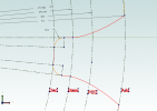
The image below is a partial of a Module 1, 20 tooth gear sketch.
I've manually added 0.3mm radius fillets to the tooth root. (0.3 dimension is arbitrary - just looked about right for this gear).
The construction circles are not needed to generate the gear but helpful when visualising some of the key features.
The construction circles are Dedendum, Base, Pitch Circle and Addendum diameters.
What I need to calculate are the centre and start/end points of the fillet arcs.
I think for the 'simple' case illustrated below the calculation should be relatively easy.
The major problem arises for greater tooth number gears where the dedendum diameter is actually larger than the base circle diameter.
Any ideas?

albie0803
Alibre Super User
With the installer, use the install for everybody option, or it writes to a user based location and it won't load. Guess how I know? 
As for your question, the radius is cut by the movement of the radius on the end of the cutter. Refer to the undercut video on the page I referenced earlier.
It can be worked out mathematically as I have a program which does it, but the maths is beyond me.
I feel it's something along the lines of plotting the position of a radiused triangular "hob" as it moves past a rotating wheel.
Properly hobbed gears will have the correct shape anyway so a place holder gear wouldn't need to be perfect.
For 3d printed gears, you could probably work the radius as a percentage of the full tooth depth as long as you limit the number of teeth for each PA to the minimum allowable before undercutting occurs.
Last edited:
bolsover
Senior Member
@albie0803
Thanks for the feedback - I'll take a look at the installer to see if there are some better options; maybe only offer the 'install for everybody'.
TBH, it was the first time I'd ever used Inno Setup to create an installer - so quite please it worked at all!
I've not thought much about the method of manufacture. I would be great to get sketches of geometrically correct gears but given that there are so many different standards and types I doubt I have either the energy or skill to get there. In the meanwhile, I'll strive to at least make representations that could be 3D printed...
David
GIOV
Alibre Super User
Hi bolsover,
You doing very well. I think you need study the geometry that oldbelt and RCH Project made time ago. They are very accurate designs in my point of view , also RCH Project did a planetary gear. I did time ago a excel linked but now with a GP(Variable) will be better.
Here is a summary of the Oldbelt & RCH Project links:
Oldbelt:
https://www.alibre.com/forum/index....ears-in-alibre-design-expert.7974/#post-46203
RCH Project
https://www.alibre.com/forum/index....n-alibre-design-expert.7974/page-2#post-91132
https://www.alibre.com/forum/index....n-alibre-design-expert.7974/page-2#post-91133
Here is my Excel linked that need to be made in GP(Variable)
1.-ParametricGearwheel-V12b.zip
Congrats an go forward!
GIOV

