What's new

locating holes on reference geometry

mmtech

Member
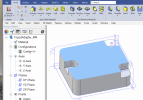
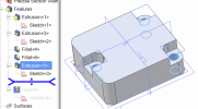
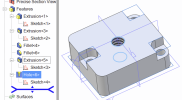
I need to create three holes in this very simple adapter. I find myself at odds with the Alibre workflow - I have to be missing something obvious.

This part will be 3D printed.

For some reason, I can't get the holes located where I need them - on the corners, concentric with the curve of the outside corner fillet.
I created reference axes where I want the axis of the holes, however I find I cannot use them. Same with reference nodes.

I have tried drilling holes, and I can't locate them on the axes/nodes I want. Nor can I apply a constraint to move them after creating them.
Same thing is a generate a sketch, enter a circle, and then try to move the circle to be either coincident with a reference axis or reference planes. I can't select my reference geometry.

This seems weird. A pointer to the right process or training would be much appreciated.
 

Attachments

  • TripodAdapter_MM.AD_PKG
    47.2 KB · Views: 11

idslk

Alibre Super User
Hello mmtech,

i'm not sure on which Alibre Version you are...(missing signiture... ;-)
So here a simple method described:

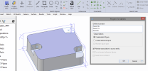
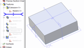
- select a face and activate sketch

1647446908109.png

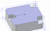
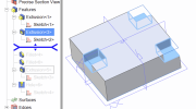
- choose project to sketch and select your three points

1647447170052.png

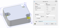
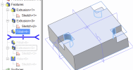
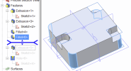
- draw 3 circles with the centers at the projected entities and extrude cut...

1647447215848.png
1647447266105.png

An easy way if you don't want to do more complicated things with this part...
Of course there are more sophisticated way's...

Regards
Stefan
 

HaroldL

Alibre Super User
I don't see any axes on the part, only points. However they can still be used to constrain the hole locations as Stephan pointed out.
Here's a video I made for another user that had a problem using the Hole Tool. Maybe there is something in it that will help with your issue.


DavidJ

Administrator
Staff member
Try a concentric sketch constraint between the corner fillet edge and your hole. That will work for the 2 holes in the corners. Not even any need for those points.

The pocket mid way along the other side has a short flat between 2 fillets, so not quite as simple - you can just use a co-incident sketch constraint with your point. No need to project to sketch.
 

mmtech

Member
Thanks Stefan - and for the signature hint.

I'm on Alibre Design 23.

So when you extruded those holes - were you able to add a constraint that centers them to the reference nodes on the top face? I could not do that. I could not select the node to center on when I made the circles for the extrusion.

I was able to - extend an axis from the node on the top face, intersecting with the face midway into the part, and then make a reference node on that face (face 19) - where the hole will start. Finally, when drawing the circle I could do a coincident constraint between the reference node on face 19 and the circle. I can see the logic of why I need a node on face 19 for the constraint. I do not understand why I can't "drill" a hole, and select a reference node for the hole placement. I have definitely constrained holes in other parts I've designed, moving them around to reference lines or lines. For some reason I can't do that now.

Here is an updated model.

This version has the three holes I wanted - done by extrusion - and a threaded hole in the center - made with the hole technique. I had to place that hole by hand and eye and I cannot figure out how to constrain it to the center of the part, designated by the intersection of two reference planes and a reference node.

What is the point of all this reference geometry if you can't use it?
 

Attachments

  • TripodAdapter_MM.V1.AD_PKG
    64.1 KB · Views: 3

mmtech

Member
@DavidJ tried that - I get "overconstrained" or "Inconsistent" sketch.

Perhaps I should have placed the holes by dimensioning via the corner or edges - and then done the fillet?
 

DavidJ

Administrator
Staff member
Over-constrained suggest there is already something else locating your hole.

As I said previously you can use a concentric sketch constraint between the filleted edge and the hole (circle or node) OR you can use co-incident sketch constraint from the point you have placed, to the hole centre or node.

When placing sketch constraints the click order can be important. First click on item that will drive, then click on item that will be driven, you may have to click in free space to clear things when moving from one feature to the next - unless you wish to 'chain' the effects (which can be useful with some constraints).

There are multiple ways you can achieve this. Constraints are usually faster than adding dimensions.
 

mmtech

Member
Have tried from scratch a couple of times. The fastest way appears to be this workflow:
1. Make the "block", with the corner fillets.
2. Locate the holes using dimensioning on the basic extruded oblong first. Create circles and extrude.
3. Use rectangles, constrain them to collinear with the sides of the block, fillet the insides of them, extrude
4. Create two reference planes to locate a node at the center of the top surface. Place the 1/4-20 hole there. I still find that I can't constrain the centerline of the threaded hole to the intersection of the two planes (or to my reference node).

At no time could I make a concentric constraint between the fillet and the center of the circle of the holes.

I'll go off and look at the video. Thanks.
 

mmtech

Member
That video was key, thank you so much.

The problem I was having was that one *has to still have the hole tool open* to constrain the hole locations - because that keeps you in sketch mode. Getting access to the constraints otherwise seems problematic.
Why did concentric constraint work to move the hole to the fillet when you clicked on the hole center *first*? That is opposite of Alibre's help - since we are moving the hole to the fillet center.
Finally, I was selecting the wrong surface for the sketch (I was using the top for some brain dead reason)
Perhaps in hind sight the thing to do is drill the holes from the bottom.

When I redid this to follow the video, I had deleted back to extrusion 3 above, so no longer had my reference planes / node for the non-corner hole. Ended up in the hole tool where reference features were turned off... so had to dimension for that one. I knew from past iterations that if I closed the hole tool - I'd lose the ability to have all the holes in one feature as you stated - great for callout.

Same thing with my center hole - had to back out, create my reference geometry, then could constrain - as long as the hole dialog was still open.

I also have been having the trouble selecting faces for holes noted here: https://www.alibreforum.com/forum/index.php?threads/trouble-selecting-surfaces.17840/#post-110259
I had to back out of hole again, and select the face for the hole first - then hole tool - and then it recognized my face selection.

IMHO the Alibre tutorials are was too simplified for these subtleties in workflow. Certainly, all the reference features should be accessible to be created or modified, and accessed at any time or mode. That is a real shortcoming of Alibre. Maybe they addressed this in v2.4, I'll go install that now.
 

DavidJ

Administrator
Staff member
You can always re-open the sketch which the hole tool creates, then have full access to all constraints, add extra holes (nodes). I often place holes roughly, close the tool then open the sketch to edit.

I'm not entirely clear regarding the logic of which constraints are directly accessible when hole tool is in use.
 

HaroldL

Alibre Super User
As to the point @DavidJ made about editing the Hole tool sketch, I should have noted in the video that you can edit the Hole tool sketch to constrain and dimension the points. But I've developed a workflow that works for me when using the Hole tool that allows me to access the constraints and dimensions.

Why did concentric constraint work to move the hole to the fillet when you clicked on the hole center *first*? That is opposite of Alibre's help - since we are moving the hole to the fillet center.
The only reason I can think of is that the fillet edge is immovable so the hole center point is the only item that can move. I have tried on several occasions the select in the order described by the manual and found that sometimes it works and sometimes not, especially when constraining a sketch figure to another unconstrained sketch figure. There are some things I just learned to work with until I get the result I need.
 

dwc

Alibre Super User
I don't understand the wish to add reference geometry when it is not needed.
Use a centered rectangle at the origin to form your piece, the hole in the middle is at the origin, all the other features are dimensioned from the edges and/or concentric from fillets.
In general think how you would make the piece manually on your workbench and do the same.
 

idslk

Alibre Super User
I don't understand the wish to add reference geometry when it is not needed.
Fully agree (same as i've done in the pictures...) would have putten a file to, but i'm on V24 and Alibre does not have the funktion to save as a former Version
It would have been better to add screenshots of the sketches also...next time :)

Regards
Stefan
 
Top