What's new

Measure tool - again.....

OrjanB

Senior Member
I constantly use the measure tool for checking distances - in both parts annd assemblies, and as mentioned in earlier threads I find the tool little intuitiv.

Here is a new odditie I ran into when making a part with several elements (cuts/extrusions/fillets)
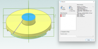
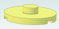
To illustrate the problem I have made this very simple part (enclosed) - a lid with 3 slots at the underside.
I want to measure the total height of the part, i.e distance between 2 paralell faces. (that I know is 50 mm)
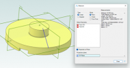
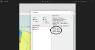
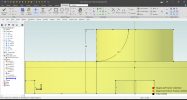
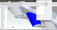
In the measure tool I mark the bottom-side and the top-side and get this (in my opinion) useless line from edge of circle to edge of circle.
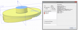
I then use the project on plane option - a new useless line occurs, and still the measurement is not perpendicular to the surfaces.
I still cannot imagine who on this planet would need these measurements (ref. my earlier thread on this theme)
In this case it I can use the x-y-z values, but with a more complicated part or angled part in an assembly it could more difficult.

Then something interesting:
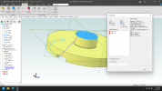
If i supress the slots the measurement can be done by using project on plane.
This means that if there are cuts (slots) in the lower surface there is no way to measure the total distance.
Am I right?

Alibre:
This is not OK - I expect to be possible to measure perpendicular distance between any paralell planes/surfaces.

So I repeat my opinion concernig the measure tool:
The default value for measuring should always show perpendicular distance when:
With 2 paralell planes/surfaces involved, regardless placement in space
With 1 plane/surface to a point or edge

Part file and pictures enclosed

Orjan

AD Expert v25 SP1
1660474345501.png
1660474358752.png
1660474372204.png
1660474384814.png
 

Attachments

  • Lokk_measure_test.AD_PRT
    341.5 KB · Views: 10

DavidJ

Administrator
Staff member
This seems to be repeating items mentioned in the previous post.

The 'workaround' is as before, add a plane to the interrupted face.
 

OrjanB

Senior Member
The 'workaround' is as before, add a plane to the interrupted face.
I know, but this workaround should not be needed.
For new users this is not obvious. The interupted face should be treated in Alibre same way as a plane.
Orjan
 

DavidJ

Administrator
Staff member
Orjan, out of interest how would you measure the real physical part? I would most likely use a height gauge on a surface plate or other flat surface (so similar my method in Alibre).

I'm not saying your request shouldn't or couldn't be done - but be wary of adding additional rules or 'intelligence' - there may be cases where that can lead to undesired results (at least for some users).

To say 'This means that if there are cuts (slots) in the lower surface there is no way to measure the total distance' is over dramatic.
 

OrjanB

Senior Member
To say 'This means that if there are cuts (slots) in the lower surface there is no way to measure the total distance' is over dramatic.
You are right - I was too strong in my writing, but still it is my opinion that adding planes are not obvious and should not be needed.
 

OrjanB

Senior Member
how should this be treated with your "standard"?
Not sure what you mean.
In my case the 2 faces of interest are paralell and I want to quicly find the distance.
In your case the bottom-face is at an angle - distance is therefore not of interest (?)
Orjan
 

Ken226

Alibre Super User
Not sure what you mean.
In my case the 2 faces of interest are paralell and I want to quicly find the distance.
In your case the bottom-face is at an angle - distance is therefore not of interest (?)
Orjan
Perhaps I am misunderstanding your question?

I opened your part and used the measuring tool on the two faces you appear to be talking about:


It shows the distance (Delta Y) as 50mm. Is this not correct?

1660485711799.png

1660485831650.png


I mentioned this same thing in the last thread and got no replies. Am I misunderstanding something here? Because when use a sketch to verify that measurement, it appears to be correct:

1660485998469.png


In this case, your part is oriented such that the Y axis is the vertical. So the distance between the two faces along Y (Delta Y) is 50mm. Is this not the dimension you were asking about?
 
Last edited:

simonb65

Alibre Super User
The default value for measuring should always show perpendicular distance when:
With 2 parallel planes/surfaces involved, regardless placement in space
With 1 plane/surface to a point or edge
+1, or at least an option in the measure dialog to force these conditions. This isn't so much a problem when the faces are also parallel to a base plane as you can use the X, Y or Z distance, but it does become a pain when the parallel faces are themselves are angled in 3D space and the X, Y and Z are no longer of use.
 

OrjanB

Senior Member
Perhaps I am misunderstanding your question?
As I said several times earlier: When the orientation is along main axis/planes I use the x-y-z values as you point out - no problem.
But sometimes the paralell faces are at an angle (i.e. in assemblies) - then it is not that obvious.
 

Ken226

Alibre Super User
As I said several times earlier: When the orientation is along main axis/planes I use the x-y-z values as you point out - no problem.
But sometimes the paralell faces are at an angle (i.e. in assemblies) - then it is not that obvious.


I can see the utility in what you are asking for. Perhaps complete the online "suggest a feature" form, if you have not already done so.

I wouldn't think it too difficult for Alibre to add a line in the measuring tool to display the perpendicular distance between two planar faces.


In the interim, until or unless they add that feature in the future

It took me about 5 seconds to add these two planes and take the measurement between them:

1660489700387.png

Then another couple seconds to delete them.
 
Last edited:

simonb65

Alibre Super User
It took me about 5 seconds to add these two planes and take the measurement between them:

Then another couple seconds to delete them.
Exactly the type of pre/post operation the program could do automatically/internally for you! ...... in microseconds :)
 

DavidJ

Administrator
Staff member
- and we covered this in the previous thread.

Clearly some people feel really strongly about this, others don't regard it as a high priority. I'm glad it isn't my choice whether to devote resource to this or not. I will again ask Product Manager to overview this.
 

kiwiavi

Member
I had a wholei lot of measurements to do on and part last week and I found it easiest was to export to DXF and use Turbocad.
It has all the features of snap to center, snap to point etc. I normally get models from clents and then need to measure to set up my machine. The export was a really good option and from there I could easily add dimensions and print.
 

Lukin

Member
Maybe one more point to improve the measurement.

When measuring I would like to use the cube in the upper right corner to rotate the view, for example normal to the plane (axis alignment), or for some other reason I would like to use the view cube. However, when a measurement is made and I click on the view cube in the upper right corner, the measured value disappears.

This does not happen when I orient the view using the yellow cubes in the upper left corner.

I don't know if this will be an improvement for other users though?

Sorry for going a little off topic, but I didn't want to start a new topic when this "problem" is also related to the measurement tool.
 

simonb65

Alibre Super User
When measuring I would like to use the cube in the upper right corner to rotate the view, for example normal to the plane (axis alignment), or for some other reason I would like to use the view cube. However, when a measurement is made and I click on the view cube in the upper right corner, the measured value disappears.
That happens because to clear measurements, you click the modelling canvas in empty whitespace. The problem is that in some scenarios, the view cube doesn't handle the users click as a command, it is see's the modelling space behind first. As an example, pan a model so that its behind the view cube, then hover over the view cube and it shows the highlighted edges of the model behind!

This is the root thing that needs fixing. That in turn would probably cause the measure tool to not see view cube clicks as clicks on modelling whitespace, because you'd be clicking on a navigation control not the model canvas!
 
Top