What's new

Meshcam Pro adding margin for inset of a part

applieddynamics

New Member
Hello,
Newbie to milling here!
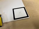
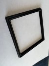
I designed a part and 3d printed it (it is an RFID antenna frame/trough) see photo black frame on white background. I want to inlay that into a piece of MDF in the other photo you can see the inlay paths in MeshCam Pro. I was able to mill it out no problem but because the inlay is the exact dimensions of the part it is too tight to fit the part. I tried to increase the scale of the part a tiny bit but then it didn't fit. I don't see anywhere in MeshCam Pro to add margins or expand the paths by some small offset. Does anyone know how to achieve this?
Thanks in advance,
Russ
 

Attachments

  • q-2.jpg
    q-2.jpg
    553.8 KB · Views: 11
  • q-1.jpg
    q-1.jpg
    574.9 KB · Views: 12

Ken226

Alibre Super User
I'm not familiar with Meshcam, so I can't help with that. I use CamBam which is so different from Meshcam that any CAM advice i give would be useless.

But, it looks like a small diameter endmill was used. They tend to flex a little during cuts, so if you didn't account for tool flex when programming your toolpaths a part can come out a little under/oversized. Usually a thousandth or two. How much undersized is the pocket? Usually this would be accounted for by roughing out the part, then programming a finishing pass that profiles the wall under light tool load.

Sometimes, in a pinch, ill simply leave the part in the same setup and run the same program again, with the same tool and the reduced tool load from the lack of material, result in the extra pass taking just a tiny bit more of the walls. Kinda a finishing run, without any programming, tool or setup change. If you only need a thousandth off the walls, another run might do it.
 

Nick952

Senior Member
A couple of options
!) If meshcam is capable, when generating the tool path, use Cutter Compensation.

2) Rather than scaling the part, enter the tool dia slightly undersize e.g. using a 6mm cutter, enter 5.98mm when generating the tool path, this will make a pocket slightly oversize, or a block slightly undersize. You can also make the cutter larger e.g. 6.02mm to have the opposite effect (Adjust the amount you change the cutter by as required)

The advantage with using Cutter Compensation, is that the size adjustment can be made in the machine control, without the need to regenerate the tool path in Meshcam,
 
Last edited:

jfleming

Alibre Super User
On a traditional milling machine you could adjust for that with the Cutter Compensation settings. I would try what Ken suggests and run it again, it may clean some off.
 

applieddynamics

New Member
Thanks guys,
I can't find cutter compensation in MeshCam Pro or much info on it for my Carbide XXL mill. I'm going to try the the tool setup of making it smaller and see if that works. I'll let you know.
Also, my worry about running it again is that I'm not confident I can find the zero center point exactly like the first run. I've been using the "make an x in the center of the piece and setting that as zero when I setup the gcode file and the mill. Does that make sense?
Thanks again,
Russ
 

Ken226

Alibre Super User
Thanks guys,
I can't find cutter compensation in MeshCam Pro or much info on it for my Carbide XXL mill. I'm going to try the the tool setup of making it smaller and see if that works. I'll let you know.
Also, my worry about running it again is that I'm not confident I can find the zero center point exactly like the first run. I've been using the "make an x in the center of the piece and setting that as zero when I setup the gcode file and the mill. Does that make sense?
Thanks again,
Russ

Given your setup zero method, I suspect a second run will definitely make it a little bigger. :)

Get a set of old style spring style edge finders. They'll last a lifetime and are pretty cheap.

Mitutoyo 050103, Edge/Center Finder, 3/8" Diameter Shank, 0.200" Diameter Tip

https://www.amazon.com/dp/B002SG7PPM/ref=cm_sw_r_apan_i_DBEFF8A2F037GKQ8PPFY
 

applieddynamics

New Member
Thanks for the tip Ken226 I'll get some of those. This will help me and the kids I coach a great deal.

So, I didn't have much luck with with finding anything in my software or mill for cutter compensation. I tried the tool diameter thing on three tests drastically reducing the diameter by the third run and had no success. Then it hit me to go back to the model of the frame I increased the height by a pretty good fraction, duplicated it twice, increased the width and length by a fraction on the first duplicate, decreased the width and length by a fraction on the second duplicate and grouped them together as one model. This gave the perfect size pocket to inlay.

I appreciate all the help. Looks like I need to learn Alibre and Fusion 360. Right now I use Tinkercad, Meshcam Pro, I'm trying out Vcarve Desktop, and Cura for slicing.
Thanks,
Russ
 

Attachments

  • mill-1.jpg
    mill-1.jpg
    481.2 KB · Views: 3
Top