What's new

O-Ring Groove on side of Cylinder????

Wing-Nut

Senior Member
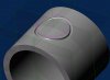
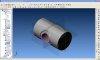
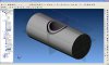
I have been attempting to place an O-Ring Groove on the side of a Cylinder with Zero Success. Any Ideas??? I am thinking there is a way to Sweep Cut the Groove but need to create Geometry for the Sweep Shape. I have tried a Booleans Cut but it isn't right. This will be done on a Rotary 4th Axis.

Is there a better way other than trying to generate a Geometry Projection around the Cylinder Surface??? Or maybe an Assembly ?? There must be a better way, and one that works for that matter.

The Shaft is about 5/8" in diameter with a 3/8" Bored Through on the Side.

The O-Ring Groove (about 1/16" wide) needs to go around the 3/8 Bore.

This one has been quite confusing at this end. Considering this is a first attempt at something like this in Alibre.

BTW V10.1 or V11.1 suggestions are all good. Just don't tell me it can't be done. :cry:
 

Uman

Senior Member
In part sketch mode, draw profile of o-ring or groove (must be a closed sketch) and perform revolve cut around the center line of the part axis.

Jeff
 

Wing-Nut

Senior Member
That would be great, but it needs to be on the side around the Cylinder. Like This but full 4 Axis.
 

Attachments

  • ALIBRE Design O-Ring-Cylinder.jpeg
    ALIBRE Design O-Ring-Cylinder.jpeg
    447.5 KB · Views: 108

MilesH

Alibre Super User
Wing-Nut,

Create a small groove, as you have in your example, and use one edge of that as the Path for your Sweep Cut.
If this initial groove section easily fits in a quadrant section of the o-ring and if one of its edges is the central Path, then it will be "consumed" by the subsequent Sweep Cut.


worm-track_method_2.jpg


:wink:
 

Ralf

Alibre Super User
MilesH said:
Wing-Nut,
Create a small groove, as you have in your example, and use one edge of that as the Path for your Sweep.

That works well Miles, but you've forgotten something: 4x exclamation mark, like !!!!
:lol:
 

Wing-Nut

Senior Member
THAT IS COOL!!!!!!!!!!!!!!!! Plus EXTREMELY CLOSE to what I'm trying to do.

I guess the best way to explain it would be to take an O-Ring and place it so that it curves around the Cylindrical Face. I have gotten close in V11.1 a few days ago but it still wrong because the Groove side walls do not follow the Cylindrical Face.

If only software could read our minds, LOL.

Thanks for the thoughts Guys.

BTW: Miles how did you do that???? That's Groovy!!!!!!!!!!!!!!!!!!!! :mrgreen: :wink:
 

MilesH

Alibre Super User
Wing-Nut,

You want the wrapped o-ring path to be circular when viewed axially, right?

Like this?
 

Attachments

  • O-ring groove.jpg
    O-ring groove.jpg
    153.8 KB · Views: 102

MilesH

Alibre Super User
Here's a quick example for you to play with (V11.1):
 

Attachments

  • O-ring groove example.AD_PRT
    480.5 KB · Views: 167

Wing-Nut

Senior Member
Thanks to Miles's Example I was able to complete the task of placing an O-Ring around a Cross Hole on a Shaft. I will have to play around with Alibre more to get used to it.

Here are the results in JPEG and Zipped File.

Thanks again for your reference model Miles.

V11.1 is working out so well on the Dell Precision M4400 I will be Upgrading all the PC's from V10.1 this Holiday Weekend.

BTW any one that is curious about their PC can check out CPUID . It tells you all the information about your PC ro Lap Top Build.

http://www.cpuid-pro.com/devkits.php
 

Attachments

  • O-RING EXAMPLE MILES_H_REF2.jpeg
    O-RING EXAMPLE MILES_H_REF2.jpeg
    525.1 KB · Views: 101
  • O-ring_groove 1.zip
    3.7 MB · Views: 114
  • O-RING EXAMPLE MILES_H_REF.jpeg
    O-RING EXAMPLE MILES_H_REF.jpeg
    445.5 KB · Views: 108

Wing-Nut

Senior Member
Here is what CPUID will tell you about your PC. There is a lot more too
 

Attachments

  • CPUID1.jpeg
    CPUID1.jpeg
    144.8 KB · Views: 101
  • CPUID2.jpeg
    CPUID2.jpeg
    105 KB · Views: 90
  • CPUID3.jpeg
    CPUID3.jpeg
    96.5 KB · Views: 98

DavidJ

Administrator
Staff member
Note that the 'wrapped' circle has a perimiter a little longer than that of the original flat circular sketch - hopefully the stretch in the 'O' ring will accomadate this. In some cases it may be necessary to correct for this by making the original cicle a little smaller than the 'O' ring which will be used. Sorry - but so far I don't have any simple guide for working out this allowance!
 

MilesH

Alibre Super User
DavidJ said:
Sorry - but so far I don't have any simple guide for working out this allowance!

I had a go at working out a formula, too, but my brain overheated :) You can get there with a few iterations and everything is associative so it's quite quick.

It would be nice if we could use an Extrude Cut rather than a Sweep Cut, to create the Path... :roll:
 

Wing-Nut

Senior Member
DavidJ said:
Note that the 'wrapped' circle has a perimiter a little longer than that of the original flat circular sketch - hopefully the stretch in the 'O' ring will accomadate this. In some cases it may be necessary to correct for this by making the original cicle a little smaller than the 'O' ring which will be used. Sorry - but so far I don't have any simple guide for working out this allowance!


This is a Very Good point.

Thankfully the O-Rings are Neoprene and will stretch a little. This is for a Valve that the Engineering Dept. is working on. Originally the O-Ring material was a type of Teflon but do to the fact that no serious heat will be coming into play Neoprene will do the job well.

That is what R&D is all about. :mrgreen:
 
Top