What's new

Problem using standard shapes

bolsover

Senior Member
While working up a design for a very simple slotted arm, I found real difficulty with use of Standard Features and particularly with the Obround shape. I'm wondering how others use these features and overcome the problems I found.

For the attached Arm.AD_PRT, I used the Obround shape for the main profile and simply anchored this to the origin to create a fully defined sketch. I would not normally anchor a line/arc like this but would instead use dimensions to define the location.

For the threaded hole, I used project to sketch on the main body right arc to obtain the centre point of the hole. - No problem.

For the slotted hole, I had expected to be able to use a similar project to sketch technique to constrain the centre of the right slot arc to the centre of the main body left arc. However this appears to be impossible; the only option being to manually calculate the location of the slot centre point.

How to others overcome this issue - or do you simply not use Standard Features in this way?
 

Attachments

  • Arm.AD_PRT
    320 KB · Views: 8

simonb65

Alibre Super User
David, for slots (of uniform width), I use a single sketch line on the centreline of the slot, then Thin Extrude Cut using the width of the slot. Followed by applying a radius fillet to the internal corners at the end of the slot. This method lends itself to curved and 'kinked' slots, as well as the basic straight slots.

Have a look at a previous post of mine ... https://www.alibre.com/forum/index....d-of-creating-slotted-holes.23112/post-154119
 

bolsover

Senior Member
David, for slots (of uniform width), I use a single sketch line on the centreline of the slot, then Thin Extrude Cut using the width of the slot. Followed by applying a radius fillet to the internal corners at the end of the slot. This method lends itself to curved and 'kinked' slots, as well as the basic straight slots.

Have a look at a previous post of mine ... https://www.alibre.com/forum/index....d-of-creating-slotted-holes.23112/post-154119
@simonb65 Nice technique.. I'll be using that!
David
 

DavidJ

Administrator
Staff member
The shape tools are a bit odd - they were added years ago specifically for sheet metal use. They behave more like symbols than like a conventional sketch.

The alternate anchor points offered can give a way to position them relative to other items, but may require a little calculation - which often negates any time saving from using the shape tool.

Shape tools also can't be trimmed and adjusted in the same way that standard sketch figures can be.

In summary - sometimes shape tools can be a time saver, but sometimes other approaches will work better.
 

idslk

Alibre Super User
I use a single sketch line on the centreline of the slot
where do you start the centerline of the slot? could you do the part file for demonstration?

Regards
Stefan

Edit:
may my question wasn't clear enough...
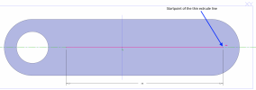
how you define the Startpoint (see picture below) of the line, to get the radius of the fillets from the slot concentic to the outer radius?
1676823297077.png
 
Last edited:

HaroldL

Alibre Super User
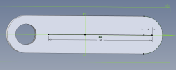
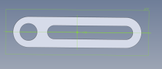
I don't mean to answer for someone else but I would dimension from the center of the end radius.
1676846033393.png

1676846055155.png

@bolsover , you should update your signature with your latest version of Alibre. I tried using v25 and got a warning that I needed v26 to open it.
 
Last edited:

bolsover

Senior Member
The shape tools are a bit odd - they were added years ago specifically for sheet metal use. They behave more like symbols than like a conventional sketch.

The alternate anchor points offered can give a way to position them relative to other items, but may require a little calculation - which often negates any time saving from using the shape tool.

Shape tools also can't be trimmed and adjusted in the same way that standard sketch figures can be.

In summary - sometimes shape tools can be a time saver, but sometimes other approaches will work better.
Thanks David
As always, lots of very helpful advice and pointers from Alibre staff and forum members.
I just wonder if these standard shapes might be made even more useful....
If I use a standard shape to create an extrusion and then project that extrusion to a sketch, I see the primitive lines and arcs used by the shape.
Would it be possible to allow 'convert to reference features' directly on the shape?

David
 

simonb65

Alibre Super User
how you define the Startpoint (see picture below) of the line, to get the radius of the fillets from the slot concentic to the outer radius?
Not at my PC right now, but to do slots in parts that accept a 'pin' from another part ...

First I edit in place (in the assembly) and project the pin onto the part I need a slot in. This gives a end position of the pin, its radius and centre position.
Then move the part with the pin (in the assembly) to the final position of the desired travel and project that to the same sketch on the part needing the slot.
Then extrude cut the end pin holes, then using those holes centre point connect a sketch then thin extrude cut in the part that requires the slot.

This approach then already has the radiused ends of the slot in the desired locations and you don't need to fillet (as that geometry is already there from the projected pin end positions and associated extrude cuts).

Hope that helps.

For the method described by @HaroldL , that works nicely on straight slots where the centre of the end pin positions can be determined either by dimension or projection as above, but for curved slots it is a little difficult.

A tool to just extend a sketch by a specific amount, rather than just extend to the next sketch figure, would be a great tool to add to the toolbox! Hint @Max !
 
Last edited:

DavidJ

Administrator
Staff member
David,

Not sure. The shapes have patterns attached (intended originally for say punched features in sheet metal) - so there is much more than a simple sketch tied up in the shape.

Short term, it might be more expedient to create some of your own Catalog Features from regular geometry. Depending upon how much variation you'll have, that might or might not work well. You can re-size catalog features after insertion by editing the sketch and applying dimensions - I just did some test with an obround / slot type catalog feature.

I can ask the Product Manager to look at this thread, but just at present there is no spare bandwidth in Development.
 

HaroldL

Alibre Super User
The shape tools are a bit odd - they were added years ago specifically for sheet metal use. They behave more like symbols than like a conventional sketch.

The alternate anchor points offered can give a way to position them relative to other items, but may require a little calculation - which often negates any time saving from using the shape tool.

Shape tools also can't be trimmed and adjusted in the same way that standard sketch figures can be.

In summary - sometimes shape tools can be a time saver, but sometimes other approaches will work better.
When Shapes were first added to Alibre I was hopeful that they would include some of the more specialized punches used in sheet metal.
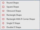
1676929120692.png
The only shapes I have found to be occasionally useful are the Obround, Rectangle With R Corner, Single D, and Double D. The Round, Square and Rectangle can all be created easily enough, and faster, with the regular sketch figures. Also, the Hole tool creates the Round, although for sheet metal it needs an option to match material thickness.

Some shapes for sheet metal, like keyways or keyholes, would be nice to have
1676929437238.png
but once you create a Catalog Feature for your particular set of punch shapes and sizes the Shapes kind of become unnecessary.
 

NateLiquidGravity

Alibre Super User
I made a script a while back that can "explode" a sketch (with shapes or text) into a new sketch that contains all the base elements (lines, arcs, circles) of the original. Useful after you have the pattern designed but you don't want some of the pattern. Explode it then delete what you don't want. The script could easily be modified to remove the Alibre Script stock copy comparison.

I'm working on a script to more intelligently automatically apply constraints and dimensions but it's not perfected yet.
 
Top