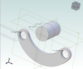
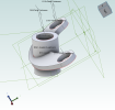
You told me up there, that I cannot rotate a part, such as the cylinder. I have to construct it this way. I thus made an axis shifted parallel to the x-axis. Then a tilted plane through it. Then construct the part on this plane. also shiftable, meaning the origin of the part parametric. Considering full rotateability, which was not required here, I'd have to come up with another plane, and another angle.. basically ending up with the Euler angles before starting with the component. Once I have such a rotatable component, I couldn't linear-array place it, unless I want their axis to be parallel. A circular array mirrors around the rotation axis, their axis won't necessarily be parallel depending on the rotation axis.
I didn't yet try to copy paste a component, if there was a copy paste at all. If their parameters were copied, they'd be the same, and not named differently.
No.. there is no copy-past for a components, such as a cylinder with a hole or such.