What's new

Sheet Metal - extrude?

WLehmann

Member
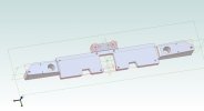
I have a mildly complex sheet metal part (image), from which I would like to derive some kind of gauge for easy quality control.
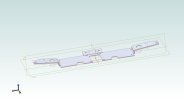
The idea was to build something like in the image below, ideally with a few reference pins added.
The problem: I could not find any way to derive the shown part within AD (expert, v24).
(The shown 'solution' has been cut with external tools from an uneven STL part - not a desirable option and a dead end.)

I tried booleans, even from contoured blocks, extruding 3D-Sketches, including simplified outlines, - I am running out of ideas.
Any hint, on how to derive the gauge part, would be highly appreciated.

Best regards,
Wolfgang
 

Attachments

  • Ctr_Plate.jpg
    Ctr_Plate.jpg
    359.7 KB · Views: 24
  • Ctr_Plate_Gauge.png
    Ctr_Plate_Gauge.png
    25.8 KB · Views: 23

idslk

Alibre Super User
Hello Wolfgang,

i made a sample part... and as far as i don't know the Version you are using i will add some pictures
first the part (not very elevat how it is made)
1647537811194.png

select the "bottom" of your part and activate a new sketch
1647537962223.png

select project to sketch and then the needed geometry
1647538107415.png

1647538212762.png

in this cas i have added the to long upper and lower edges as lines manually...
1647538297792.png

then choose from the extrude feature from the ribbon and there Type "To Next"
1647538406539.png

1647538489068.png

Hope this is what you want to get...

Regards
Stefan
 

HaroldL

Alibre Super User
Remember to cut away the sheet metal part after the extrude To Next as it becomes part of the extrude. For the gauge to fit a formed part the original shape needs to be removed. You could do a Boolean Subtract with the original part.
 

WLehmann

Member
Hi Stefan,
many thanks for your effort and quick response! Yes, THAT's what I'd expect. :)

I actually had not turned on the 3d-Part Editing in sheet metal design and had to search for it.
Nevertheless, it's not working as you describe / intended - the OK button gets RED as soon, as I select more than 1 flange.
I tried a sketch on the bottom of the part as well, as using a slightly offset plane.
I also only used the flat central part and the two larger flanges, for simplicity. It works as described with one flange, but not more.
I'll attach the original part now - please ignore the bits & pieces, it's basically fitted to housing and electronics.

I am still trying alternative approaches (re-import from SAT) and simplifications, but without success.
The sketch seems OK (xx closed loops) but refused to extrude 'to Next'.

Regards,
Wolfgang
 

WLehmann

Member
I just removed the complex sheet metal part from above - too much distraction.

Here's a simpler test-part, that shows the same effect: I can extrude a sketch to one flange only.
Once you select sketches under >1 plane of the sheet metal, it'll fail.

@idslk : could you please upload your part, which looks very similar, but works?
 

Attachments

  • Extrude2SheetMetal_test.AD_SMP
    319 KB · Views: 3
Last edited:

idslk

Alibre Super User
Hello Wolfgang,
here a file for the "fixture", based on your simple part:

1647551940512.png
Regards
Stefan
 

Attachments

  • Extrude2SheetMetal_test_fixture.AD_PKG
    70.9 KB · Views: 5

WLehmann

Member
@HaroldL : many many thanks for that big effort! Much appreciated.
I think, that's the 'manual' version, I was trying to avoid, lazy as I am. ;)
Nevertheless, it seems a safe way to the desired goal.

@idslk : thanks for posting! This seems to work as well on my side.
I need to figure out, what goes wrong and when I guess, in more detail, later.

Best regards,
Wolfgang
 

WLehmann

Member
Quick update from the original part:
I tried the intended extrude (which seems to work under certain conditions, above) very carefully.
It seems to work like a charm, IF there is one closed loop for the contour, and as many holes inside that loop as you like - image attached, Hooray!

Feeling adventurous, I tried to remove some holes in a later step (edit sketch - marked in image) - the whole extrude fails without apparent reason.
There was actually no way to make the sketch extrude again, beside deleting the sketch and projecting and editing the whole geometry again.
Interestingly enough, also leaving the same holes out in an initial projection step will cause the extrusion to fail.

I think, I stop poking into internal issues here, acknowledging that this might be a borderline use-case.
A (even elegant) solution is possible, but I would not not built a larger design on the interim result.

Thanks again for the assistance,
Wolfgang
 

Attachments

  • SheetMet_Fixture_02b1.jpg
    SheetMet_Fixture_02b1.jpg
    52.8 KB · Views: 9
Top