What's new

Showing weld seams on folded sheet metal parts

Rudy

Member
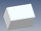
Just wondering if anyone knows of a better way to show weld seams on folded aluminum parts that have been modeled as a sheet metal part. The material thickness I'm using at the moment is 4.7 mm. I realize there are annotations available but they don't show the physical seam. The voids where the folded tabs meet don't look proper unless they show the actual weld joint. Right now I'm creating the weld seam as a separate part with multiple configurations depending on the length and adding it as an assembly but that is a bit tedious. It's also a pain in the BOM (no pun intended) as it will show up there also.
Any insights into this would be greatly appreciated.
 

HaroldL

Alibre Super User
I think the only solution is the one you came up with. There is no WELD BEAD generator in Alibre.
In my previous employ we did a lot of sheet metal design using SolidWorks and we did not show the weld bead on any of the models, only the weld symbols on the drawings. It wasn't until we started to use KeyShot to render catalog images that I came up with a way to model the weld beads and render a "completed" model. Up until that time the images showed open weld seams. :rolleyes:
The method I used was similar to what you describe. I models each weld bead as a separate component in an assembly configuration. And it is tedious to have to add the seams manually.

Maybe something could be done with a script, if any of the script gurus are up to the challenge that I think it would be. Maybe something similar to what SolidWorks came up with. But even SW didn't have a very convincing graphics display of the weld bead.

Do you have a screen shot of what you're dealing with?
 

Rudy

Member
OK, thanks for for the feedback. It's kind of what I expected; I just wanted to make sure I wasn't overlooking any features. I think a script would be extremely helpful and would be a good solution but I'd have to get into things much deeper and don't have the time for that right now. I don't really care what the weld looks like as long as something reasonable is there. I was looking into using surfaces (still haven't quite figured that out) but that likely would not work. I was hoping that there was some sort of texture feature similar to when a cross-section is shown with a specific pattern or the shading representing threads on 3D parts.
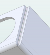
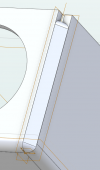
Anyway, this is the situation, without and with; the weld part isn't quite long enough, has to be adjusted. There is a bit of an issue with the fillet on the ends of the weld part as it does not match the bend radius. For some reason a larger fillet radius causes an error if it is much larger but for now it seems close enough. If it bothers me enough, I'll find a way to add a surface texture similar to the shading on the thread feature to make it look a bit more "real".
1655236953017.png1655237568254.png
 

Rudy

Member
Thanks for that; good explanation. That would also work. Linear Pattern could be used to fill in the other corners.
 

Ken226

Alibre Super User
Thanks for that; good explanation. That would also work. Linear Pattern could be used to fill in the other corners.

The mirror function would be good for that as well. Mirror one side to the other, then mirror the top two onto the bottom.
 
Top