jcdammeyer
Senior Member
Is it possible to create a toothed timing belt that connects two pulleys and then turn one pulley and have it move the belt and turn the other pulley?
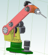
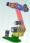
You can see in the screen shot where I want to put the L series belt. Not that it's needed for animation. But it would make the model cooler. I can't figure out how I'd make these constrain with the gear constraint.Use the gear/pulley constraint to get the wheels turning in sync, the timing belt, you may have to just use your imagination a bit.

Going to have to find a tutorial on the gear constraints then. So far it doesn't work with the toothed pulleys.The gear constraint isn't for constraining the belt in place, it will only allow the two component gears to move/rotate in relation to each other within the ratio selected. The belt will be stationary since it is not "flexible" and will not move and will require other constraints to position it.
Awesome. I'll try that. Thank you.Activate the gear constraint, pick a circular edge for each gear, eg the bore.
In the gear size fields, put the number of teeth for each gear.
Hit OK then grab one of the gears and rotate it. The other gear will rotate accordingly.
10 and 10 will give you a 1:1 drive. 20 and 10 will give a 2:1 drive
If the "driven' gear is going the wrong way, then edit the constraint and tick the reverse rotation box.

Yahoo. Worked like a charm. For belts and pulleys have to click the reverse box. Now I can turn the motor pulley and watch the arm move.Activate the gear constraint, pick a circular edge for each gear, eg the bore.
In the gear size fields, put the number of teeth for each gear.
Hit OK then grab one of the gears and rotate it. The other gear will rotate accordingly.
10 and 10 will give you a 1:1 drive. 20 and 10 will give a 2:1 drive
If the "driven' gear is going the wrong way, then edit the constraint and tick the reverse rotation box.
Activate the gear constraint, pick a circular edge for each gear, eg the bore.
In the gear size fields, put the number of teeth for each gear.
Hit OK then grab one of the gears and rotate it. The other gear will rotate accordingly.
10 and 10 will give you a 1:1 drive. 20 and 10 will give a 2:1 drive
If the "driven' gear is going the wrong way, then edit the constraint and tick the reverse rotation box.
