What's new

[Solved] Preventing Alibre from Rounding

DavidJ

Administrator
Staff member
So this change seems to be a side effect of the DoF callout.

I didn't see it because I don't normally use DoF callout. It seems that the way DoF callout interacts with Precision is different to the standard Dimension tool.

At least I understand what is happening now.- I'll log this for investigation.
 

Jake_Steidy

Senior Member
Nate, personally if I change from 3 decimal to 4 decimal during testing there was no difference in length of the two lines, so no problem occurred with that 4th decimal.

David, thanks for logging it, just wanted to bring it up seeing how often I run into it using 1/16 fractionals.

Thanks everyone,
Jake
 

OTE_TheMissile

Alibre Super User
Late to the party but FWIW, stuff like this is why I always model using the maximum 6-place precision, then do all my actual prints going out to the floor with their normal 2 or 3 place precision. Bury any kind of rounding errors so far past the decimal that they're irrelevant, and my prints come out just right every time (usually:D)
 

Jake_Steidy

Senior Member
Mike! Welcome! Curious how you deal with all those decimals on your dimensions when within a 2D drawing? Are you using zero suppression? I've just used 3 decimals for so long, even testing out the 4 decimals yesterday really had the gears smoking up top. Thanks for joining in, I'm always appreciative of other user's styles or best practices.
Jake
 

DavidJ

Administrator
Staff member
Jake, precision settings for 2D drawing are independent of those for the model. So design at higher precision, then set 2D drawing precision for how you like to see it displayed.
 

OTE_TheMissile

Alibre Super User
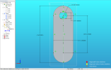
What DavidJ said. For example, here's the Sketch of a simple flat tab for a weldment I drew yesterday:
43TREF43FQER.png

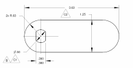
And then here's the view on the print that goes out to the floor/our outside vendor:
4TWREF43ER.png

I'm the only one doing CAD where I work so it's just me that has to deal with whatever's inside the 3D models. I tone it down on my prints for Joe Public.

EDIT: I'm also just now realizing I should've made that 2x R.63 a reference dimension on the print. Already submitted it to Management though. Oops
 
Last edited:

Jake_Steidy

Senior Member
Guess I'm a bit confused by what you mean with that. Since some of my older replies to this thread detailed how changing that original File properties > Units > General > Display Units > Precision from 3 to 4 doesn't create the line length increasing problem. So it would seem to me that it isn't independent when changing from 3 to 4 decimals, if that is supposed to just be a visual change. In that the 4th decimal drawing doesn't create the line that lengthens itself, when I take that dimension leader I am presented with the correct length as the original line. Maybe I'm just not understanding what your saying, and apologies for that.

Yeah my prints are definitely different than what I'm designing Mike! Luckily where I'm at I have limited CAD to customer need, more so just CAD to other engineers at different fabricators.

Thanks guys,
Jake
 

OTE_TheMissile

Alibre Super User
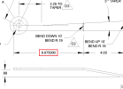
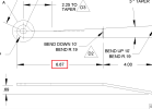
On a barely-related note, I still sometimes run into situations like this where a dimension on my print that definitely should've rounded up due to precision, doesn't. No apparent rhyme or reason to it, and even if I try to fudge the value higher in my model it still won't tick over until I'm almost at the digit being shown in the print. Seems to happen most often with Sheetmetal (and usually when dimensioning bend lines), but to me Sheetmetal design is a "give it your best shot and then beat it in the rest of the way with a hammer" process anyway so I just chalk it up to that. Plus my build of Alibre is going into 4 years old so that's probably not helping either.

6.875000" rounds to 6.87" on the print. Same model, same print, same dimension, only difference between these two images is the dimension's precision level:
342erwsd.png123ewqsd.png
 

Jake_Steidy

Senior Member
On a barely-related note, I still sometimes run into situations like this where a dimension on my print that definitely should've rounded up due to precision, doesn't. No apparent rhyme or reason to it, and even if I try to fudge the value higher in my model it still won't tick over until I'm almost at the digit being shown in the print. Seems to happen most often with Sheetmetal (and usually when dimensioning bend lines), but to me Sheetmetal design is a "give it your best shot and then beat it in the rest of the way with a hammer" process anyway so I just chalk it up to that. Plus my build of Alibre is going into 4 years old so that's probably not helping either.

6.875000" rounds to 6.87" on the print:
View attachment 35610View attachment 35612
Mike, this is definitely something I have experienced with sheet metal as well. The best part is when some of those dimensions round up on one part, and then on the next part they don't, even occurring on the same drawing detail, and like you said you can't just force it to round up or down. I just chalk it up to the quirkiness of Alibre.
Jake
 

DavidJ

Administrator
Staff member
Guess I'm a bit confused by what you mean with that. Since some of my older replies to this thread detailed how changing that original File properties > Units > General > Display Units > Precision from 3 to 4 doesn't create the line length increasing problem. So it would seem to me that it isn't independent when changing from 3 to 4 decimals, if that is supposed to just be a visual change. In that the 4th decimal drawing doesn't create the line that lengthens itself, when I take that dimension leader I am presented with the correct length as the original line. Maybe I'm just not understanding what your saying, and apologies for that.

Yeah my prints are definitely different than what I'm designing Mike! Luckily where I'm at I have limited CAD to customer need, more so just CAD to other engineers at different fabricators.

Thanks guys,
Jake

Jake - the 'change' seems to happen if using DoF callout to apply the dimension. It seems to take the display value and set the dimension to it, whereas the standard dimension tool takes the underlying value and sets that (if you open a dimension it displays to more places than the display precision if required).

The 'problem' is specific to use of the DoF callout tool to set dimensions, when precision is set to less places than the underlying values need.

Personally I'd turn off DoF callouts, and just use an 'equals' sketch constraint or the standard dimension tool.
 

Jake_Steidy

Senior Member
David, Thanks understood. I was originally confused with the DoF callout you mentioned, but now I know what you mean. I will stop using those and change my workflow to use either equals or just the standard dimensioning tool. I'll let you know if I see any other cases where this pops up! Thanks again everyone!
 

HaroldL

Alibre Super User
What is your result going from 4 places to 3 places in display settings.


1647528148821.png


Personally I'd turn off DoF callouts, and just use an 'equals' sketch constraint or the standard dimension tool.
As a point of reference, I haven't used the DoF callouts for quite a while, I can see there usefulness but I think they just clutter the screen with all those callouts. It would be better if the callouts were near the sketch figures they are related to but they seem to just be scattered all over.

I use real time dimensioning and key in the values I want or need while sketching if I know them. And those that I don't know I just go back and apply dimensions and constraints as needed.
 

idslk

Alibre Super User
Hello Harold,

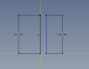
try to set your precision setting to 3 first, then draw the line, type in the 4 digits length of 0,0625 (which will automaticaly displayed as 0,063), do the offset and use the DOF callout which will show 0,063 and press enter. The behaviour here is the same as Jake has described. If you change then the precision from 3 to 4 digits, on dim will show 0,0625 and the other one will show 0,0630.

Regards
Stefan
 

HaroldL

Alibre Super User
OK, got it. The issue is that the DoF is adopting the three place value of the dimension instead of the four place value of the line length. If the line is offset it should be the same length as the original no matter the number of places displayed by the dimension. I missed that part in my demo video.

Something needs fixin' here.
 
Top