What's new

Spline editing - Reverse engineering

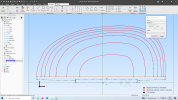
I am reverse engineering a part from an image. The part is a cylinder head for a motorcycle where all the fins are curved wth a different profile. There are seven profiles, each with 15-20 points. I have managed to create a respectable copy of the fins which then, individually, become a cutting extrusion to create the final shape of a 3d model. The sketch I have used is 60+ years old and is lacking in dimensional data. It appears that the drawing may have been scaled or suffering from a parallax issue, from copying badly, in one area. As a result to match the rest of the CAD model I need to shift some of the control point in one direction by controlled amounts - tantamount to a linear scaling from a set point. Click and dragging 150 points and maintaining shape consistency is a daunting prospect. Can I export the points in a CSV file, effectively reversing the processing of adding nodes with a CSV file? I can't find anything in the documentation about doing this.
I need to gain about 1.5 mm in 120mm.

In the Alibre I have been able to interrogate the points, but I don't get X-Y data - just a box with an X value and a Vector. I don't think this is enough to create a file from.
If I have to go back to basics to create a 2d spline, am I using a 2 word format (X and Y) for each point? Is a Excel file exported in CSV format acceptable?

In investigating this I did notice some typos in the documentation.

How to Modify the Shape of a B-Spline

Section 3
Select the Insert Knows tool to insert new knots on a curve know vector without changing the curve shape.


Hope you can advise me.
Regards
D
 

stepalibre

Alibre Super User
Sketch insert nodes:
1713723905774.png
And Alibre Script can help you generate sketches from external data.
 

stepalibre

Alibre Super User
In the Alibre I have been able to interrogate the points, but I don't get X-Y data - just a box with an X value and a Vector. I don't think this is enough to create a file from.
If I have to go back to basics to create a 2d spline, am I using a 2 word format (X and Y) for each point? Is a Excel file exported in CSV format acceptable?
More information would help.

I often draw something in other applications (QCAD or Rhino) and export points to txt files. And with AlibreScript/API or Insert Nodes from File generate sketches.

If you need a high level of control of the geometry it might be best to use Alibre Script or the API.
 

stepalibre

Alibre Super User
If you have existing splines within an Alibre sketch, here is an example of AD_BSPLINE data that you can process externally, exported using the API.

ControlPoints: 7.808, 1.221, 9.23340678149799, 0.722778825394047, 12.0475281216672, -0.260838523549207, 1.47605446142238, -2.53392711766249, -1.43918407857503, 0.823033909639998, 2.7249635035406, 0.26267885478935, 4.677, -6.22119083860282E-17
Poles: 7.808, 1.221, 9.23340678149799, 0.722778825394047, 12.0475281216672, -0.260838523549207, 1.47605446142238, -2.53392711766249, -1.43918407857503, 0.823033909639998, 2.7249635035406, 0.26267885478935, 4.677, -6.22119083860282E-17
Knots: 0, 0, 0, 0, 0.250609759862992, 0.494768428521135, 0.76316150010485, 1, 1, 1, 1
Weights: 0, 0, 0, 0, 0, 0, 0
Parent Sketch Name: sk1
Parent Sketch Plane: XY-Plane
Type: AD_BSPLINE
ID: 1
 
More information would help.

I often draw something in other applications (QCAD or Rhino) and export points to txt files. And with AlibreScript/API or Insert Nodes from File generate sketches.

If you need a high level of control of the geometry it might be best to use Alibre Script or the API.
I hope this puts some context to the original post.
The screen dump covers the seven upper profiles on the original engineer's sketch. The guy who did the sketch (60 odd years ago) had access to the manufacturing and development drawing information for the item.
The points in the X- direction need to grow in proportion by approximately 1- 1.5 mm. The Y values will be held constant. If the profiles alter noticeably I can mess around with the contours/points/knots etc .

Thanks for the help
D
 

Attachments

  • Head_Profiles_1.png
    Head_Profiles_1.png
    194.7 KB · Views: 10

stepalibre

Alibre Super User
Thanks. I'm not sure if AD sketch tools will work here. It might be better to develop the curve you need externally and insert as nodes. If you have a based curve you can export the data to a txt file for Excel. Apply the x increase by 1 -1.5 mm, etc. Export to txt file and use insert as nodes. I don't do much spline work inside AD, others may have a solution.
 

HaroldL

Alibre Super User
The sketch I have used is 60+ years old and is lacking in dimensional data. It appears that the drawing may have been scaled or suffering from a parallax issue, from copying badly, in one area.
Are you tracing the image or sketching from data points on the drawing?

n investigating this I did notice some typos in the documentation.

How to Modify the Shape of a B-Spline

Section 3
Select the Insert Knows tool to insert new knots on a curve know vector without changing the curve shape.
Send this to Support along with link to the Help section. They should be able to get it corrected.
 

stepalibre

Alibre Super User
Would dimensioning the y and changing the x -direction with parameters work better than the Move Curve Points?
 

stepalibre

Alibre Super User
Dimensioning each node? Alibre has limited spline editing tools.
1713731640574.png
 

Attachments

  • spline-editing.AD_PRT
    247 KB · Views: 2
Are you tracing the image or sketching from data points on the drawing?


Send this to Support along with link to the Help section. They should be able to get it corrected.
I'm tracing the pencil sketch using the image facility to create an Alibre Sketch. There are no data points on the drawing. I'm confident about the scaling involved in that process as there were some dimensions written in pencil - certainly enough to be confident about the majority of dimensions used.

I'll re-send the typo issue as you suggested. Thanks for the help.
 

stepalibre

Alibre Super User
I'm tracing the pencil sketch using the image facility to create an Alibre Sketch. There are no data points on the drawing. I'm confident about the scaling involved in that process as there were some dimensions written in pencil - certainly enough to be confident about the majority of dimensions used.
You can create a new sketch and project the traced profile that you need to modify in the x-direction. Then dimension a new spline with nodes. If you want to use a CSV file you still can.
 
Dimensioning each node? Alibre has limited spline editing tools.
View attachment 41568
This looks to be the answer - I like straightforward solutions. I've never tried to dimension a spline - so obvious.
I have my Alibre on a separate Desktop but put my cries for help are tapped out on this laptop - so I'm doing some reading about Python Scripts, API and other stuff. The solution I'm going to try is to breakout a spline to make a small model *.AD_PRT file - one that contains just the single 2d sketch. The file will be easy enough to open in Notepad ( I've checked that). Then change the points, one at a time, checking that the expected changes occur in the AD_PRT file. The 'BSPLINE' word appears very frequently - so it should be a simple task to find the relevant data sections
If they do, I can put them into an Excel file to do the arithmetic, then put them into CSV file. Then I can load the CSV into each relevant 2D sketch. this means I can edit the shapes more easily, with traceability.
I realise I can go directly to the dimensions I need from the process you suggested. But if I can get them into a file as well I know I can modify them more easily, and keep control of them.
Thankyou very much for the simple suggestion.
Much appreciated,
D
 

HaroldL

Alibre Super User
Depending on the shape of the cooling fins you could try using a series of Tangent Arcs instead of a spline. I've done that before with satisfactory results, especially if the edge profile is not critical.

Another option is to convert your image to a SVG, there are some free converters online, then import that into your Alibre sketch via the RMB.
Here's a screen shot of the Right mouse menu, at the bottom is the Import SVG.
1713751186184.png
 
Last edited:
I have followed StepAlibre's advice and created a spline using Nodes. It is the same procedure as a regular spline in that you are selecting a point in the Tracing Image by eye, and clicking. The difference is that no spline will be created at that point, just a series of unlinked Nodes. The spline is created by selecting the spline tool (first item in the Spline List) and a start point, then clicking on the Nodes in succession, then an end point. The Nodes can be dimensioned before or after the Spline is created - it doesn't matter. I left the start and end point so that a base or anchor point on a regular feature is created when using the Spline tool. It fixes the Spline - allowing it to slide along the feature (if using a line) but no other way.
The dimensions can be found in the equation Editor as usual. The awkward thing is getting the Equation Editor to do what the V27 guide says - that is to export the data. Importing seems easy, but going out of the system is proving difficult. Quote below.
V27 Manual : Equations can be added, deleted, imported, and exported in the Equation Editor dialog box.
If I can get that data out of the system I can achieve the rest of the task easily.

HaroldL has suggested I use an SVG file. I'm game to try anything - would Inkscape be a good option to work with as part of that journey? I've not used vector graphics much.

Thanks again to the continued advice,
Regards,
David
 
Top