For most applications little more than a call out tag with the respective thread details is needed when designing and detailing part drawings. Sometimes, however, the devil is in the details and things such as threaded surfaces can make or break a finish rendered part. Of course you can use a helical cut to design in your own threads when making a part, but that can be time consuming. Recently I was working on a design using extruded aluminum profiles and I needed one end of a few pieces tapped to an M8x1.25 thread. Because the extruded aluminum already has a hole through it, it seemed redundant to make a hole callout putting the same size hole on top of the existing hole. Not only that, but in my drawing it doesn't really do it justice for the guy that was going to make the part and it would be easy to "accidentally" tap the wrong end. Since my finish model already had the bolt that would go into the threaded hole in it, I quickly thought, hey.. why dont I just do a boolean subtract and use the actual bolt model (courtesy of McMaster-Carr) to create the actual thread detail. It was as simple as pressing the boolean subtract button, constraining the bolt in the extrusion, and checking the green check mark. Simple and good looking thread detail.
You are using an out of date browser. It may not display this or other websites correctly.
You should upgrade or use an alternative browser.
You should upgrade or use an alternative browser.
TIP: Aesthetic internal threads made easy
- Thread starter cleschak
- Start date
RocketNut
Alibre Super User
cleschak said:For most applications little more than a call out tag with the respective thread details is needed when designing and detailing part drawings. Sometimes, however, the devil is in the details and things such as threaded surfaces can make or break a finish rendered part. Of course you can use a helical cut to design in your own threads when making a part, but that can be time consuming. Recently I was working on a design using extruded aluminum profiles and I needed one end of a few pieces tapped to an M8x1.25 thread. Because the extruded aluminum already has a hole through it, it seemed redundant to make a hole callout putting the same size hole on top of the existing hole. Not only that, but in my drawing it doesn't really do it justice for the guy that was going to make the part and it would be easy to "accidentally" tap the wrong end. Since my finish model already had the bolt that would go into the threaded hole in it, I quickly thought, hey.. why dont I just do a boolean subtract and use the actual bolt model (courtesy of McMaster-Carr) to create the actual thread detail. It was as simple as pressing the boolean subtract button, constraining the bolt in the extrusion, and checking the green check mark. Simple and good looking thread detail.
WOW never thought about using the BOOLEAN SUBTRACT tool to make threaded holes by using the bolt as a tool.
+++++1
RocketNut
Alibre Super User
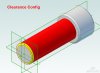
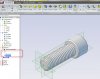
I'm changing my fasteners to there (McMaster Carr) STP file. With one simple change. I used the config function to create two configs. One I call "THREADS" and the other called "CLEARANCE" which has the STP threads cover up (see attached screen shot). I have attached part file shows how I did it. I also noticed there is hardly any lag compared with the helix function made threads.
I feel this has to rank right up there with the best tip in this forum.
I feel this has to rank right up there with the best tip in this forum.
Attachments
RocketNut
Alibre Super User
jhiker
That's correct.Just as DavidJ said is ether greyed out or not depends on what configuration you select. Please take a look at the attached screen shots. As you can see if the THREADS is selected then the thread cover is grayed out. The if CLEARANCE is selected the the thread cover is not grayed out and the threads are hidden thus making a clearance hole for the bolt. .
That's correct.Just as DavidJ said is ether greyed out or not depends on what configuration you select. Please take a look at the attached screen shots. As you can see if the THREADS is selected then the thread cover is grayed out. The if CLEARANCE is selected the the thread cover is not grayed out and the threads are hidden thus making a clearance hole for the bolt. .
Attachments
Lew_Merrick
Guest
Before you go too nuts over McMaster-Carr's models, remember that they have a number of design inaccuracies included to identify their models if and when they decide that you have violated their usage policies that requires you to specify the parts by their part numbers.
1) Their models rarely include the head to shank fillet and, when they do, the fillet is set to something less than Maximum Material Condition.
2) The depth of thread is often quite a bit deeper than specified by the appropriate standards.
Otherwise, they are fine and this approach works. (Remember that the Hole Preset System allows you to create drill & counterbore holes quite easily.) The problem with this approach is the model size growth it engenders. I would certainly limit it to a visualization configuration and use cosmetic threads for parts going into assemblies. The (if you will) patch surface representing the thread should be visible in the model and exported as a cosmetic thread entity through STEP. It is not, after all, as if you are going to constrain a screw's threads to a tapped hole -- and the "overlap" will show up as an interference when checking.
Lew,
While I appreciate the input on the McMaster Carr model inaccuracies, please note that I titled this as "Aesthetic internal threads". This was not intended to be geometrically perfect, but to add detail for final concept rendering and presentation. In manufacturing there is indeed no need for an aesthetic thread on a print or in a model as that can be handled in the callout using the hole tool as you mentioned, but sometimes designers need to show off their design and sell it to the customer. The small details in these cases can make all the difference once rendered and that was what this tip was intended for. In the case of a rendered model with lighting and materials applied, nobody is going to pick out the subtle inaccuracies of the McMaster-Carr part. Also, the tip is using the boolean feature and some other model to do work for you.. McMaster-Carr was just a reference of one of many places where part models are readily available for download. You could very easily design all your own threads *once* and save those into a file to use later on if your really are worried about being perfect.
Again, appreciate the insight, but its a bit off of the intended topic here.
Lew_Merrick
Guest
Cleschak,
If you noted, I did provide the caveat: I would certainly limit it to a visualization configuration and use cosmetic threads for parts going into assemblies.
One of the companies I work with that likes to use the McMaster-Carr screw models just (as in over this past weekend) had the model growth that is one of my most serious concerns about such things crash a major project model because they were using such geometry rich screw models. 64 GB of memory was not sufficient to load their top installation model. This panic was (relatively) easily solved by replacing their aesthetic screws with cosmetic thread screws. I see this several times each year and operationally unnecessary geometry is the cause. This is why I suggest using configurations to limit the progression of unnecessarily geometry rich elements while maintaining overall model integrity for assembly.
To be clear, I construct (limited) thread geometry when applying left hand, Acme, or other not completely common threads to provide a smack up the side of the head visual feedback to those doing the manufacture. It is not that I oppose use of aesthetic threads, merely that the downside of such use be made clear.