What's new

Tips and Tricks:

indesign

Alibre Super User


Add more emocons

You must have a link to emocons. You may sign up to another forum or search the internet for them.

I use the cadcam trainer forum.

When adding them to the post you must surround them using the "Img" format or it shows up as a link. Surround the http link to the image by clicking the Img button before and after the link.

http://www.cadcamtrainer.com/forums/ima ... jparty.gif

To get the http link of an existing emocon simply right click the emocon and select Properties.

djparty.gif
 

OTE_TheMissile

Alibre Super User


Here's a neat one I stumbled across: If your files have long names (such as the ones I do here at Rivco: "GL18007-10 FRAMEBRACE RIGHT HAND") and you don't feel like retyping that whole thing when you save the drawing that goes with your model, in the Save or Save As menus just click on the filename for the model, as if you were trying to overwrite it. Alibre knows the difference between model files and drawing files, and instead of overwriting it'll copy the filename and give it the proper extension.
 

NateLiquidGravity

Alibre Super User


Solid Part Modeling In Sheet Metal Mode
Here is one I did not find on this list, but figured out how after reading a comment about using solid part modeling in a sheet metal part. Results of using the two in combination are not optimal (read as: may result in error) but may solve a tricky problem for you.

Solid part modeling features are located on the Feature menu under Features.

Solid Part Modeling Toolbar In Sheet Metal Mode
Right click on any toolbar and check "Part Modeling".

Done. Now you can quickly use some of the solid part modeling features.

I'm sure the experts here knew this one already but for a new guy like me it might help.
 

Ralf

Alibre Super User
Editor: Threads and Material

Editor for Alibre Design as Freeware -> Threads and Materials.

Download Editor

Ralf

(Editor is no longer available.)
 
Last edited:

Hobelman

Member


Faster respons of explorermenus:

This is a workaround for the right click menu delay in the explorer on big assemblies: switch to Wire Display (View > Display > Wireframe) and activate the Display Acceleration (View > Display Acceleration or icon). In this way the viewport is still shaded but the delay is gone.

There is no effect in Vista because this delay only occurs in XP.
 

OTE_TheMissile

Alibre Super User
Did anybody know that if you start a sketch on a plane and it appears in the wrong direction (i.e., you're looking at the back of the part instead of the front), you can immediately flip it around by clicking the "Orient To Sketch Plane" button while the view is still oriented to the sketch plane?

Found that out totally by accident 8)
 

OTE_TheMissile

Alibre Super User
Boy I'm on a roll with the T&T lately :D

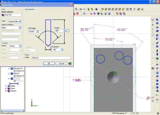
Maybe this has been addressed in v10 or is being worked on for v11, but in v9.2 I always found it cumbersome to do bolt-circle patterns using the Hole tool. When making the Sketch for placing the holes, the only tool that isn't greyed out is the Node. So no way to generate a reference arc or any reference lines to establish the angle of the first hole.

Today I got a project with a B.C. pattern that had no holes directly above or next to the B.C. center, and not evenly spaced. It suddenly dawned on me a way to workaround the limitations of the hole sketch. I just placed one hole for starters more or less where I wanted it without dimensioning it, and clicked OK. Then, I right-clicked on the hole's Sketch in the Design Explorer. Now I've got all my tools 8)

Drew my B.C. and converted it to a reference figure (through the right click menu), and drew reference lines from the center to the B.C. where each hole would be, and dimensioned the angle they made. Exit Sketch mode.

Right click on the Hole feature in Design Explorer and select Edit, and taadaa, now I've got my B.C., reference angles, and all the endpoints I need to properly locate the holes.

bc_in_hole.jpg
 

wathavy4

Alibre Super User
The cam curvature is named Modified sinusoidal curve in my text book.
The formula may be obtained from books.
The excel graph shows that my input was ok. :wink:


EDIT 2010 Dec 07
Applied with CycloidGearReducer by bemfarmer
viewtopic.php?f=10&t=12064
 

Attachments

  • BasicCurvatureCalculation.png
    BasicCurvatureCalculation.png
    29.2 KB · Views: 496

dmckee101

Alibre Super User
Re: Tips and Tricks: Creating Revision Markers

Alibre has a utility for creating Custom Symbols that can be used to create revision markers for drawings. I'm sure you could use these custom symbols for other purposes as well.

The process (for doing it in a drawing) is like this;
1)Activate sketch.
2)Draw the marker shape you want.
3)On menu under "Sketch>Text> Field" add a Field and place it in the shape you just drew. (This is the same way you would add a field to a drawing template.)
4)Under "Sketch>Create Custom Symbol" choose the lines of the shape and the field you added and save.

Now that it's saved you can insert it anytime, any drawing.

A)Open a new drawing and activate sketch.
B)Under "Sketch> Insert Custom Symbol" in the dialog box choose your new symbol and pick a point to insert.
C)You'll get a popup box to edit the field (just like fields used in title blocks). No exploding, no scripts.
 

indesign

Alibre Super User
Display dimension in BOM from equation editor

This works for "design dimensions" added from a solid to a drawing or any parameter in the equation ediotor.

In a BOM

Edit>Insert Column

Click Custom
Chance the Data Type to Parameter
In the Property change thr name to that of the equation name from the equation editor you wish to display.
Click OK

Now you display a dimension (or calculation) in the BOM! :D :D :D

ralf3 said:
 

mkent

Senior Member
Generating points for import

I found a nice graphing program that will let you generate a curve of any math function.
You can define the extents and the increments for the curve and a list of points will be generated in .csv format or others.
The points can then be brought into Alex's "Point Import Wizard" and plotted in Alibre.
http://www.dplot.com/?source=dplot
 
Top