Ah, one other that I just realized about... Multiple constraint.....
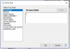
Suppose you have a large number, say 30 pc, that all need to be on the same plane, the ability to select a "multiple constraint" and then mark each of the surfaces that you want coincident on the plane, one on each of the pieces, and then have the "execute" or "OK" button apply the lot at once would be really extremely useful.*
I see this as the first selected is the "master", and the others selected would be then constrained to it, and move to conform to the constraint.
There is the question of whether this is a single constraint, or if it appears in the tree as a number of them.
I think it should appear as a single constraint, editable. And, when edited, any individual surface can be deleted from the list, except the original "master" surface or plane.
I confess I have not yet thought out which constraints this should be possible with, and which it conflicts with.
However, I initially think it has to be possible with "coincident" constraint with a plane, and therefore also for an offset of the same type. I cannot immediately say why it should not be possible with anything that "coincident"applies to.
Fastener, that is just not possible in my view, because you have a multiplicity of BOTH destination references and object references. This depends on ONE destination reference and multiple objects.
Coaxial, that should be possible, given suitable objects.
Angle.... maybe, but I do not forsee all the ramifications clearly there
Tangent, I think yes.
I do not think there is any way to do this now, or if there is, it is not findable in the help
* Imagine, for instance, that you are doing a facility layout. You have a large number of "things" that need to be constrained to a floor plane, which are perhaps all different, so an "array" is not applicable. You will have a huge number of constraints applied just to get the items down on the floor, and then you start locating them.
Much simpler to collect a lot of constraints in one place by the "multiple constraint", and a much cleaner design tree.