What's new

Why can't I apply constraints

laverne3ca

Senior Member
I downloaded an assembly in Alibre format from a site and want to modify it and am having issues when I remove one part and replace it with a modified version of the same part. I'm trying to replace the end cap of this part with the one I've added lettering to.

I'm using Alibre Design Expert Version: 25, latest build
 

Attachments

  • N2 AVS-3312-24D.AD_PKG
    472.8 KB · Views: 5

Ken226

Alibre Super User
I downloaded an assembly in Alibre format from a site and want to modify it and am having issues when I remove one part and replace it with a modified version of the same part. I'm trying to replace the end cap of this part with the one I've added lettering to.

I'm using Alibre Design Expert Version: 25, latest build

I didn't have any trouble. I deleted the unmarked endcap and constrained the marked version in its place. Is this what you had in mind?
 

Attachments

  • AVS-3312-24D.AD_PKG
    462.3 KB · Views: 2

HaroldL

Alibre Super User
As Ken said, just delete the one without marking and constrain the one with marking in its place.
I had no problem using the Replace Assembly Component method either.
One thing you may want to do is constrain the main assembly to the default planes. I was able to move it all over the workspace when I opened the assembly. That's never a good thing when putting an assembly together.
 

Ken226

Alibre Super User
Just to add to what Harold mentioned. In case you're not familiar with the methods of doing this.


It's easy to constrain faces of the part to the default planes, That will lock it in place and everything you move/constrain after will be easier:

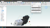
Another method I use alot is to right click and select "show reference geometry", Then you can constrain the reference planes coplanar to the assembly default planes while keeping the part symetrically centered with respect to the default plane.
1660773828341.png


There may be other methods for doing this, but as a matter of habit i usually constrain the reference planes of my main/primary part to the assembly default planes pretty early in the assembly process.


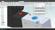
Another example:

That little red button was also floating free. I right clicked it, selected "show reference geometry", then constrained its reference planes to the main housings reference plane to center it, and constrained its other vertical reference plane coincident to the cylindrical hole.
1660774827576.png
 

Attachments

  • AVS-3312-24D.AD_PKG
    467.8 KB · Views: 0
Last edited:

simonb65

Alibre Super User
One thing you may want to do is constrain the main assembly to the default planes. I was able to move it all over the workspace when I opened the assembly. That's never a good thing when putting an assembly together.
Another approach is to add the first part by placing it at the origin, then anchor it before you add and constrain other parts to it.
 

HaroldL

Alibre Super User
I've gotten used to just mating two axes of the main/primary part to two axes of the assembly workspace. That locks down all six degrees of freedom of the part.
From there I use the Show Reference Geometry of all parts to constrain the remaining components. Now that there is a toggle for them I will sometimes turn off the default workspace planes after locking down the main then just use the parts reference planes and axes for the remaining constraints. Then if the whole assembly needs to be moved or reoriented, which may be a rare occurrence, the first two axis constraints can be suppressed or deleted and the assembly moved and reconstrained as needed.
 

laverne3ca

Senior Member
Thanks everyone. had tried variations of every suggestion with the exception of Replace Assembly Component without getting it to work, not sure what the difference is but now it works! Thank you, again!
 
Top