What's new

Yet another question about Sweeping, but this time with a Twist

Tentimes

Member
Hi Brains Trust,

Has anyone found a successful method for sweeping along an angled circle, but keeping the shape parallel to a plane?

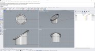
In the drawings below, the first pic is there just for perspective, so you don't end up as confused as I am.

Imagine a spiral staircase. Each step is slightly higher and rotated around the Y axis, yet the tread of the step remains nice and flat.
I need to achieve the same thing, but with a continuous surface.

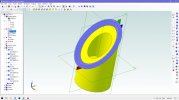
Referring to drawing #2:
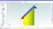
I want to sweep shape A around the outside radius of the tube, where it's cut at 45 degrees, but have the item remain parallel to the ZX Plane, so it ends up at position 'C', rather than 'B'
The mauve feature is, of course, what happens with a conventional sweep, using the outside edge of the sloping circle as a path.

Currently using a ancient version (Expert 2011).

Any thoughts?
 

Attachments

  • 01.jpg
    01.jpg
    136.5 KB · Views: 30
  • 02.jpg
    02.jpg
    119.5 KB · Views: 30

DavidJ

Administrator
Staff member
Can probably be done with loft, using plenty of profiles and a guide curve.

Someone will maybe suggest a simpler option.
 

HaroldL

Alibre Super User
Thought I'd try this with a loft. I got half way around adding the sketches and Alibre froze up as soon as I selected sketch<7>. This was my second attempt, the first one just crashed Alibre when trying to add a final sketch to close the loop.

1660467143864.png
 

DavidJ

Administrator
Staff member
I had no problem forming a loft, but with 4 profile sketches around the tube, there was still some distortion - hence my comment about 'plenty of profiles'. I used edge of the tube as a global guide curve.

Symmetry should allow use of less profiles, then mirror the result.
 

idslk

Alibre Super User
After examinig the first loft_test it had some face distortion, so i did another attempt...
Include an precise section cut at an angle with no scetch to see how it behaves...
1660482130578.png
1660482235250.png
 

Attachments

  • Loft_test2.AD_PRT
    851.5 KB · Views: 6

HaroldL

Alibre Super User
Well with all the success I see others made on this loft I gave my model another try. Of course it failed again, froze up Alibre just by adding the sketches, didn't even get to add a path.
So I recorded a short video so what I did could be reviewed by others and maybe point out an error I may have made that caused the freeze up.

Here's the link to the video:


and here's the model with all the sketches and path as shown in the video.
 

Attachments

  • sloped loft.AD_PRT
    319.5 KB · Views: 5

idslk

Alibre Super User
Hello Harold,

trying to create the loft as you, ends up here as well in a frozen Alibre :)

i've tried your part and while trying to create the loft in a different order, it stops letting me add another sketch. It deletes the preview build up to the last added sketch and disables the ok button.

1660506804957.png

1660506770686.png

Then i have suppressed the slanted cylinder and tried to loft only the rectangular sketches,. This "works", but doesn't closes the round and won't let me select a guide curve...

1660506410369.png

It does not freeze, but works not as expected...

Adding another sketch on the "back" of sketch<2> fills the ring but leaves a dogleg there...

1660507359653.png

and it doesn't let me add a guide curve.

Sorry, but no further idea:(

Regards
Stefan
 

HaroldL

Alibre Super User
Yeah, this sounds like a Support issue. I'll send this to support and see if they can find out what's going on.

BTW, one of the "enhancements" to Loft was the addition of the Ends options (Enden) that eliminates the need for a final sketch to close the loop (your sketch<2>). In this case Alibre didn't let me add enough profiles to even try the Ends options.
 

NateLiquidGravity

Alibre Super User
I'll not sure what exact shape you are going for. That said maybe try a mid extrude across the whole thing with a sketch shaped like this _/‾ and then cut out the middle and make it a circle on the outside? Add some variable radius fillets to round it out.
 

HaroldL

Alibre Super User
This sounds similar to another loft issue you had back in April of 2021.


Ken226

Alibre Super User
Closest I could get was doing half of it, then mirroring it to the other half. No locking up though.

1660520830719.png
 

HaroldL

Alibre Super User
I like the solution that Stefan posted. I'm not quite sure why that one works but the one I made does not. Christina from Support thought that the model I sent in was getting confused by some of the references being the same planes and couldn't resolve them. She was going to talk to someone else to get their input and send it to Development.

It would be interesting to analyze the differences between the two models to try and understand if not the correct way but a preferred way to create this kind of loft. I'm sure it, or something similar, may come up again and it would be nice to have a method in place to create it.
 

Latitude

Member
Wonder if there's a way to make the helical boss not twist like this?

1660655184656.png

I get this error trying to change the start transition or flat angles.
1660655268075.png

And changing the end results in this weird artifact.
1660655423140.png

File attached if anyone wants to play with it.
 

Attachments

  • Helix.AD_PRT
    355.5 KB · Views: 3

HaroldL

Alibre Super User
I don't think using the Start and End Condition will help in this model. Those settings are typically used when creating springs to give them flat ends.

Here's an example from one of my recent projects:

1660666864762.png

And after trimming the ends the final result:

1660666994131.png
 

idslk

Alibre Super User
I don't think using the Start and End Condition will help in this model. Those settings are typically used when creating springs to give them flat ends.
me too :)
...but i couldn't resist my curiosity...

(sorry for the funny partnames, there is no loft inside - only helix and mirror... it'warm here in my work room...) ;)

1660671821108.png

well, it looks not that good, but it should be enough for my curiosity :)

Regards
Stefan
 

HaroldL

Alibre Super User
A suggestion from Christina in Support was that to eliminate the sharp angle where the two halves of a mirrored loft meet is to create the lofted feature with two lofts and to start them off center. That works but then you end up with a flat spot at the top and bottom of the lofts.

1660711334564.png

Just my opinion, but taking a closer look at the half loft used for mirroring, the loft could do a better job of following the guide curve. If it did then maybe the angle between the two halves of the mirror wouldn't be so noticeable.
Mirrored Loft.png
 

Attachments

  • sloped loft by two lofts.AD_PRT
    982 KB · Views: 0
  • sloped loft wMirror.AD_PRT
    423.5 KB · Views: 0

Tentimes

Member
Wow, go away sailing for a few months and the smart ones keep not only finding solutions, but asking questions I didn't think to ask.
Thanks everyone for your thoughts and suggestions. It's made me feel so much better, as I thought I must be a complete idiot that can't perform a simple task.

I managed to loft a shape that is a good approximation of the item required, using 4 drawings at 45 degrees, then mirroring the other half. It's fine for developmental purposes, but nowhere near good enough to send to CNC.
As the finished item will be a component in a very high RPM engine, accuracy will be essential.
The only other thought I had would be to plot a $hitload of points in 3d, then join them all together.
But this would need two things I don't have...
(a) someone capable and willing to do all the calculations
and
(b) a whole lot of spare time.

Once again, many thanks to everyone who has contributed so far.
 

Nick952

Senior Member
I gave up trying this in Alibre and decided to try it, as a first serious play with my recently acquired Rhino7.

With no real experience, after only 5 min I came up with this, using Rinos version of Sweep.

Edit:- I've added the Rhino file for anyone that might be interested.
 

Attachments

  • Flange - Rhino.jpg
    Flange - Rhino.jpg
    379.8 KB · Views: 39
  • Flange.3dm
    219.2 KB · Views: 2
Last edited:
Top