What's new

Exactly what can be referenced in reference planes/axis/points.

beefy

Senior Member
Alibre Expert v27

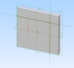
So I create a 100 x 100 square, extrude it 10mm and I have a flat square "slab".

I insert 3 reference planes:
1st 20mm offset from side edge
2nd 20mm offset from top edge
3rd on the flat 100 x 100 surface

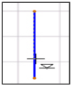
Just for the heck of it, I also insert an axis at the intersection of the two planes that are offset from the side edges.

I TRY to put a reference point at the intersection of all 3 planes but cannot find a way to do this.

I go to sketch on the surface where I put the 3rd reference plane, and I want to use the new reference planes and axis to reference my sketch. However, these planes/axis may as well be invisible, as the sketch tools do not "see" them.
So what exactly are reference planes and axis used for ?
 

Attachments

  • REFERENCE GEOMETRY.AD_PRT
    246 KB · Views: 3

beefy

Senior Member
UPDATE:

I've just found out something. I never realised you can use Project to Sketch and use the axis to project sketch lines. However, could not project planes.

So at least that is one way of using the axis to drive sketch geometry, but it's quite a pain because I have to find geometry, and/or create reference planes to make the axis, that I then use to project withing the sketch.

Having searched online I found a few forum posts on the same subject. If the ability to use reference planes in sketches has not been implemented by now, I'm guessing it may never be.
 
Last edited:

DavidJ

Administrator
Staff member
What are you actually trying to achieve here?

You can add a point where Axis 5 intersects Plane 5. Thought there are simpler ways to position a point there...


Examples of uses for planes & axes - to define revolves or mirrors, as intermediaries in defining difficult geometry.
 

beefy

Senior Member
Hi Dave, thanks for the info.

Apart from just learning the software and what can be done (which for me is the more important part), it was for one of the hardest exercises done in the Tootalltoby competitions.
Ex Machina Engineering had this one on his Youtube channel (
) and I was trying to model it before watching how he did it in his video.

I know there may be simpler ways to do something but you don't always learn software the best by taking the simplest route.
As a non-expert I'll no doubt try things that an expert wouldn't do but in the process I'll learn a lot better how things work.
 

HaroldL

Alibre Super User
BTW, did you watch any of the training videos that are available on the Alibre web site? Although the one on creating planes is pretty basic and should do more that just mention there are more ways to create planes, there should have been a demonstration of each method. Why couldn't it take a few minutes to fully describe each method of the Create Plane tool?:rolleyes:
 

Ken226

Alibre Super User
BTW, did you watch any of the training videos that are available on the Alibre web site? Although the one on creating planes is pretty basic and should do more that just mention there are more ways to create planes, there should have been a demonstration of each method. Why couldn't it take a few minutes to fully describe each method of the Create Plane tool?:rolleyes:

I made one awhile back. I think.


Yea, here it is. V24, and still using Windws 7, so quite awhile back.


beefy

Senior Member
Thanks guys.

Harold, my issue was not so much creating planes but wondering if they could be used in sketches. Example, I use Fusion at work, and where a plane crosses a sketch plane/face, you can project a line onto the sketch at that point. However, with Alibre, it seems you have to create a 2nd plane on the sketch face, then create an axis at the intersection, and only then can you project that axis onto a sketch. No idea when that would be useful, just playing with things.

Ken, I just gave the first thumbs up for your planes video, great stuff. I'll be looking at more of your vids.

I've never heard of Rumble but I'll certainly be checking it out. Already created an account.
 

DavidJ

Administrator
Staff member
However, with Alibre, it seems you have to create a 2nd plane on the sketch face, then create an axis at the intersection, and only then can you project that axis onto a sketch.

No need to create 2nd plane - use the plane or face that you will sketch on to create axis (must be done before entering sketch mode).

No need to project the axis - just use it directly in the sketch to dimension from or constrain to (any projection needed happens automatically)
 

beefy

Senior Member
Thanks David, learnt something there.

What I've been trying to do is use the axis when creating the sketch entities, but when sketching that axis is "not noticed". So I would project the axis to the sketch then created the sketch entity using the projected line.

However, definitely much cleaner creating the entity at some random position then constraining it to the axis. Cheers.
 

DavidJ

Administrator
Staff member
Axis is noticed when sketching, BUT you may have to adjust point of view slightly to be able to select the axis if it is hidden by an edge on plane or by the existing solid.

Rotate workspace a little, or pan/zoom to see where axis extends beyond model.
 
Last edited:

beefy

Senior Member
Double and triple checked mine, and sketching does not see axis. Even when I go off the sketch plane and hover over the axis, it is not seen.
The only thing I get while sketching is an inference line to the origin point.

Basic selecting works on an axis and so does using the axis for sketch constraints, but I get zippo with sketching unless I project the axis.
 

DavidJ

Administrator
Staff member
Maybe you can clarify what you mean by "not noticed", and "sketching does not see axis"...

What is it you want to do with the axis? I can constrain to and dimension from axis in sketch mode.
 

beefy

Senior Member
OK, took a lot of hunting to find the mouse/cursor symbol I get during sketching, when the cursor "sees" a line for instance.

I've attached 2 images. One is 3D so you can see the 2 reference planes and 2 axis I've created in the upper right part of the flat plate.

I created a sketch on the flat face and placed the single vertical red line there. When I say then use the circle sketch tool and move over the sketched red line, the ON THE FIGURE symbol (see attachment) appears at the curser. This is what I mean when I say something like the sketch tool "notices" or "sees" the line, or the axis, etc. If I was to click on that red line while the ON THE FIGURE symbol was there, then the circle centre would automatically be constrained to that line.

However, the ON THE FIGURE symbol does not appear when I move the cursor over any of the reference axis I created. This is what I mean by "not noticed" or "sketching does not see axis".

It's no big deal though, because I can get around this with constraints, projections, dimensioning, etc, to the axis. When I first started this thread I didn't realise I could do all that.
 

Attachments

  • 3D VIEW.png
    3D VIEW.png
    69.4 KB · Views: 10
  • ON-THE-FIGURE SYMBOL.png
    ON-THE-FIGURE SYMBOL.png
    15 KB · Views: 10
Top