What's new

I wish Alibre had an easier way to dimension a 2D drawing, maybe as easy as the method used in Shaper3D.

DavidJ

Administrator
Staff member
I didn't post any images - I think you mean HaroldL.

The nodes only appear (sometimes) during dimensioning. I wouldn't worry too much about whether they appear or not.

I think somebody really needs to see what is (not) happening - it may be a good idea to raise a ticket with Support.

One more thing to try perhaps - you could re-set the Alibre user profile (using link on Utilities Tab of the Home Window).


Can you dimension in 2D drawings of other models, or do all 2D drawings have the same problem? There are some aspects of this model which if not quite to the (less than totally clear) instructions, could make dimensioning problematic.
 
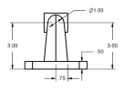
I'm having the same problem with the dimensioning of all 2D drawings in Alibre. It seems to be very hit and miss: some dimensions appear when I use the "Reposition Design Dimensions" function as I did here:

1702306133535.png

Some of these dimensions are useful (although I don't understand why the "3.00" is appeaing twice. That's minor issue though, as I can delete one of them).

My bigger problem is that I can't add any other dimensions to the drawing, for example the witdth of the cylinder at the top of the immage above, or the 2.50 inch distance between the top of the plate and the center of the hole in the cylinder.
 

DavidJ

Administrator
Staff member
Do NOT use 'Design Dimensions' - they will only confuse you at this stage. Do you mean 'Reposition Dimensions' OR 'Reproject Design Dimensions' ? - they are very different functions.

Are you activating the Dimension tool when you try to place dimensions? I presume that Annotation visibility is toggled ON.

To dimension boss width, you should be able to simply select the top most line in your view.

Dimensioning to the centre of hole in the boss is best done in the Front view (so you can select the circular edge of the hole). 2.5" would be a redundant dimension (not good practice).
 
I meant 'Reproject Design Dimensions', not 'Design Dimensions'. Not familiar with 'Design Dimensions' at this time. I'll have to read up on that subject when I get home from the office.

I can confirm that the Annotation visibility was toggled on. I had never used it before, so thanks, that's a new function I've learned.

I can't select the top most line of the boss. That seems to be the problem. Sometimes, a line such as the one we are currently discussing seems to go from black to a dark brown (I am a little colour blind) and sometimes when I move the cursor a bit, that brown line turns light blue, but still no luck adding a dimension.

Agreed with the last point that the 2.5" would be redundant. I was using it as an example: theoretically, I should be able to place that dimension, but I'm not getting that option. It does give me the option to assign a diameter to the boss, and add a center mark to it, but from there, I can't add the 3.0" from the center to the base.
 

DavidJ

Administrator
Staff member
Design Dimensions are those that you entered whilst doing the 3D modelling. They also inherit their position on the drawing from wherever you placed them in sketches etc. That usually means they won't appear anywhere sensible - so many of us rarely if ever choose to show them in 2D drawings.

Manually adding dimensions to the 2D drawing gives you much more control.

Your biggest issue seems to be selecting figures in the drawing. Do you also have problems dimensioning sketches or selecting when 3D modelling? Is the problem confined to 2D drawing workspace?

Is Windows up to date? You've already checked drivers. I wouldn't expect this model to tax any reasonably modern system, even with an integrated graphics card.

I suggest opening a support ticket,

send in DXdiag and MSinfo32 logs which will fully describe your system

This might need a screen share session with support to get to grips with things.

It's odd that you have the same problem with 2 different computers. I suggest that you create a Package File from a drawing where you have problems selecting, and include that with the support ticket (just in case there is some file corruption or similar confusing matters).
 
No problems inserting the dimensions in the 3D sketches. That part of the software works very well. It's just selecting the figures in the 2D drawings.

Anyway, I am sort of glad to hear that this is a ME problem and not a broader user wide/software problem.

I'll open a trouble ticket as you suggested and thanks for the help.
 

HaroldL

Alibre Super User
I noticed in DavidJ's 3:33 AM post that in his screen capture, there appear to be orange(?) dots or nodes appearing in his A-A section view and towards the front of the base plate.
Eh, that was me. And the screen shot was taken when I was editing the section view.

@DavidJ , I just sent in my package file. Odd that this issue is on two different computers and in two different countries. :confused: :confused:
 
Make that three different computers. I use Alibre on both my MS Surface and my home desktop.

Anyway, putting in a trouble ticket soon. Just working on the wording to try making my problem as clear as possible.

Thanks all for the tries to help.
 

DavidJ

Administrator
Staff member
Harold's section view issue was down to how he'd modelled the part (as he has already shown earlier in this thread it doesn't quite match the e-book example).

Eric - I strongly suggest that you include a package file in your support ticket (or post it here if you prefer) - so that the part file can be either ruled out, or confirmed as the cause.
 

DavidJ

Administrator
Staff member
Eric,

I really meant a Package created from the 2D drawing.

I did find that in both sketch 3 and sketch 4 the circles are slightly off axis - fixing both with constraints / dimensions allowed me to subsequently dimension a section view in the drawing.
 

DavidJ

Administrator
Staff member
As already mentioned sketches 3 & 4 not on axis, height of sketch 4 not fixed in the model.

Section lines in 2D drawing not in locations directed in the exercise and hence in the transition zone of the loft, so can't dimension. Putting section lines in directed locations fixed that.

I had no problem adding dimensions to the other views including width of boss, corner rad, hole size, hole spacings.

Try those adjustments and see where you get to.
 
Fixed the issues in sketches 3 & 4, but that didn't solve my issues dimensioning it in 2D. I can't position the section lines in the 2D drawing as shown in the exercise, probably for the same reason I can't insert dimensions in a 2D drawing. That reason being my cursor doesn't allow me to select most things in the 2D environment. I still can't place most dimensions, more frequently the linear ones. For some reason, I seem to be able to dimension arc radii and circle diameters.

So I guess I'll submit a trouble ticket.
 

HaroldL

Alibre Super User
Harold's section view issue was down to how he'd modelled the part (as he has already shown earlier in this thread it doesn't quite match the e-book example).

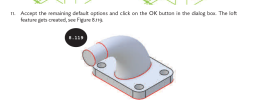
I went back and remodeled the part, following the steps in the manual, and get the same results. When the loft tool is used there is no image of what the "remaining default options" are used when the manual was created. I've already posted what I'm getting but what did they use when creating the manual?


1702401495612.png
 

DavidJ

Administrator
Staff member
Harold, I've used some different loft options - none give problems as long as
* Sketches 3 & 4 centred on axis
* Both circles are at same height
* Section lines are positioned as per instructions

I'll try to look at the file you sent to support when back at my computer... It has been a busy day here....
 

DavidJ

Administrator
Staff member
Harold,

2 things

1. your section line was not in position called for in the exercise.
2. your section view was not a removed section views as called for - not really sure why that should make such a difference, a 'standard section view' looking in the opposite direction does allow dimensioning.
 

JimCad

Senior Member
Harold, I've used some different loft options - none give problems as long as
* Sketches 3 & 4 centred on axis
* Both circles are at same height
* Section lines are positioned as per instructions

I'll try to look at the file you sent to support when back at my computer... It has been a busy day here....

I remember years ago with Inventor when picking up someone else's drawings that I could not select things to add dimensions.
I found out that the inserted views were not square to the drawing sheet.
Is this what you're saying David?
That although the drawing is square on, some of the features are not so Alibre thinks they're ISO views so it can't pick them for dimensions.
Jim
 
Top