Iam_second
Member
How do I make a solid from a 3D sketch? The Sketch field remains blank when I try to select it.

Use a combination of 2D and/or 3D sketches to create lofts, which will form the solid organic shapes you're after.I am basically trying to create a 3D shape that can be a basis for a cover (skin) for custom electronic components. It seems that this should work in 3D sketch mode because all of the 3D tools for boss, revolve, loft, etc. are available (not grayed out).
What is the purpose of 3D sketching if you cannot make a solid from them?
I haven't got one to hand, but the concept is like creating a ships hull. Use 2 or more 2D sketches to define a profile, then using one or more 3d sketches to define the guide curve that blends between the 2d sketches. Have you got a picture or can you share a hand drawn sketch of the kind of solid shape you're trying to achieve?Do you have an example of a loft created from a 3D sketch? I was using a "spline by reference points" tool to connect the points in 3D sketch mode.
Thanks...
And sweeps...Use a combination of 2D and/or 3D sketches to create lofts, which will form the solid organic shapes you're after.
That won't work. You need to start with a solid and then cut it with two sweeps (in perpendicular directions) to create the shape you want. After that shell to get the thickness.Simon
I was trying to use the Extrude Boss tool on this 3D sketch. I just want to make it 0.1" thick to use as a cover for some electronics. Thanks...

Do you have an example of a loft created from a 3D sketch?
Lofts is not the way to do this. Start with a solid block, then use two perpendicular sweeps to create the shape you want. Then shell to get the thickness.Hi Simon,
Do you have an example of a loft created from a 3D sketch? I was using a "spline by reference points" tool to connect the points in 3D sketch mode.
Thanks...
I added the 3dm file too. You can use that.Hey seb, are you using Beta build 22.0.0.22037? Build 21034 won't open a newer version.
I added the 3dm file too. You can use that.
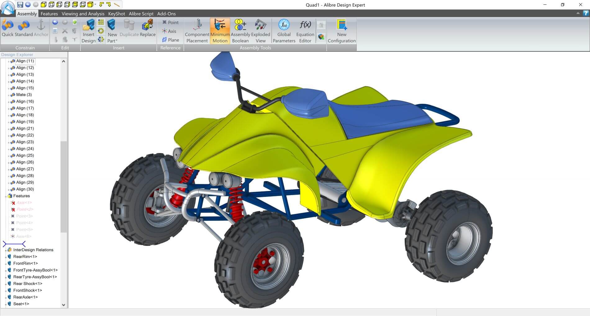
Alibre used to have a Quad Bike model that you could down load to see how the modeling was done. As I recall the hood was created as a solid then a couple of lofts defined the shape. Finally it was shelled to the final thickness.Hi Simon,
Do you have an example of a loft created from a 3D sketch? I was using a "spline by reference points" tool to connect the points in 3D sketch mode.
Thanks...
There was also a red motorcyle front fairing, and I searched everywhere for it yesterday as it was the first example I thought of too, that demonstrates the steps for creating organic lofts, cuts and shells.Alibre used to have a Quad Bike model that you could down load to see how the modeling was done. As I recall the hood was created as a solid then a couple of lofts defined the shape. Finally it was shelled to the final thickness.
Here is Simon. It is a really good example.There was also a red motorcyle front fairing, and I searched everywhere for it yesterday as it was the first example I thought of too, that demonstrates the steps for creating organic lofts, cuts and shells.
