What's new

Aligning sketch with feature surface

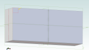
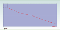
Is there a way to begin drawing on the surface of a feature and have your drawing snap to the edges of the extruded feature? For example, I made a cube in the attached file in v26 expert. I am trying to draw another rectangle on the surface of the extruded cube and will use it to remove a piece of what I just extruded. This is to make room for a screw hole as shown in the attached "model" image.

The issue I am having is that the rectangle I drew on the surface is not aligned with the edges of the extruded cube. This means the piece I remove from the extruded cube won't be the correct size because the sketch is misaligned. When in sketch mode there is no option to snap to anything except what is in the current sketch.

I didn't see anything similar in the getting started videos but if there's a demo somewhere I missed, I'd gladly take a look at it.
 

Attachments

  • Model.png
    Model.png
    145.1 KB · Views: 33
  • Sketch not aligned with feature.png
    Sketch not aligned with feature.png
    12.5 KB · Views: 34
  • Sketch on surface of feature.png
    Sketch on surface of feature.png
    240.9 KB · Views: 33
  • Sketch to Cut feature.AD_PRT
    250.5 KB · Views: 5
Last edited:
Apply Collinear constraints between the lines and the edges of the part.

View attachment 38153
Do you know why selecting parallel results in an over-constraint warning? I was trying parallel instead of collinear.

I was also trying to mirror the sketch into the bottom right corner. Drawing a diagonal line and mirroring across it doesn't result in the drawn rectangle appearing in the bottom right corner. It appears floating somewhere off the right on the bottom left. If I was intending to mirror to all 4 corners, that is no problem or put a 2nd rectangle on the bottom left or top right. But only bottom right is stumping me.
 

Attachments

  • Mirror Corner.png
    Mirror Corner.png
    74.6 KB · Views: 16
Last edited:

H.C

Member
use the project to sketch to project the feature lines >> the rectangle will snap to the corner. (don't forget to remove the projected lines after you draw the rectangle!!!...be sure...!!!)
mirror over z & then over x, remove z one :)
Cheers!
 

HaroldL

Alibre Super User
Constraints can throw some odd errors occasionally and I don't understand why, just how to work around them when they come up.
I recorded a short video to go over some of the points made in this thread, hopefully it answers your questions.
I will point out though that is may be preferred to mirror features instead of sketches. mainly because mirrored sketches are not easily edited, they sometimes need to be deleted and recreated. With a mirrored feature you only have one sketch to edit


Here's the part I created in the video.
 

Attachments

  • Sketch to Cut feature-mirrored.AD_PRT
    278.5 KB · Views: 4

HaroldL

Alibre Super User
use the project to sketch to project the feature lines >> the rectangle will snap to the corner. (don't forget to remove the projected lines after you draw the rectangle!!!...be sure...!!!)
mirror over z & then over x, remove z one :)
Cheers!
If you are going to project sketch figures, constraint the rectangle to them, then delete the projected lines, the rectangle will no longer be constrained to the corner. If you are going to project edges to a sketch for constraining purposes then use the Reference Geometry option in the project dialog. You won't need to delete them.
 

H.C

Member
oh, project as reference figures. Overlooked that :) thx

(2 corners can be removed with the move face)
 
Top