What's new

Angle Distance Chamfer: Am I missing something?

rmcard

Member
Granted, I've had Alibre/Geomagic Design for several years but I just haven't used it that much. So there's probably a simple answer to my question.

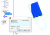
I'm trying to create a chamfer between two round extrusions that I want to be driven by 1/2 of the difference between the two diameters along with an angle other than 45 degrees. Simple enough to do using the equation editor but the ONE option the chamfer tool does NOT provide is choosing what side it applies the distance and what side gets the angle (or, at least I'm Not seeing it). Of course it defaults to the exact OPPOSITE side I want to use and I've wasted over an hour trying to figure it out, doing help searches AND typing this post. I'm going to use the Distance/Distance option just to get thru it but I wanted something that would automatically update if I choose to modify the diameters in the future.

(If I knew how to do it I'd insert that animated GIF of the little stick figure guy beating himself to bloody death on his computer keyboard here)
 

DavidJ

Administrator
Staff member
Yes - angle/distance chamfer decides for itself which way to apply. Often not the way you want.

A 'reverse' button or similar would be very helpful.
 

rmcard

Member
Well, I did manage to figure out how to partway get to what I want by doing a distance/distance and incorporating the tangent of the angle I wanted into the calculation of one of the distances, but when I got it to work it appears that the final result ended up being half the angle that I plugged in. And when I attempted to readjust by typing in different angles into the equation my result would disappear. So, I think I'm still missing something.

I've attached the file in case someone wants to mess with it, but I'm tapped out. My head hurts. Maybe I'll revisit it later.

P.S. The feature is "Edge Chamfer 5"
 

Attachments

  • Loc Pin.AD_PRT
    321.5 KB · Views: 20
rmcard said:
Well, I did manage to figure out how to partway get to what I want by doing a distance/distance and incorporating the tangent of the angle I wanted into the calculation of one of the distances, but when I got it to work it appears that the final result ended up being half the angle that I plugged in. And when I attempted to readjust by typing in different angles into the equation my result would disappear. So, I think I'm still missing something.
The thing is that the Equation Editor is exceptionally strongly typed! You will need to perform your trig calculation as a Scale and then multiply it times 1 unit (in, mm, etc.) to turn that Scale calculation into a Distance value. The alternative is to replace tan(60) with 1.732051 in your definition.
 

Dirfeldt

New Member
Well, you can add me to the complaint list too!
this angle - distance chamfer is a joke. It gives you so much more work.

I hope 3Dsystems are going to fix this soon. I am beginning to look at Inventor....
 

JST

Alibre Super User
I think you are looking at this wrong.

The chamfer tool IS COMPLETELY CONSISTENT WITH THE FILLET TOOL. They really are two versions of the same tool, differing in the shape of the result, in one case curved, in the other straight,

For an outside angle, BOTH ARE SUBTRACTIVE relative to the outside surface of the solid. They remove material to form the fillet / chamfer.

For an INSIDE angle, BOTH ARE ADDITIVE relative to the outside surface. They add material to form the fillet / chamfer.

In fact, this is 100% consistent. In both cases the action is such as to "blunt the selected angle".

It's wrong to consider that they "always do the opposite of what you want". The real problem is that you don't want what they do, or at least you expect the chamfer to do something different. But if you consider the action that the command consistently takes, you see that it is possible to know what it will do, it will always act to "blunt the angle" by removing the edge you have selected.

If you pick the inside angle between the smaller diameter and the radial face, you seem to be expecting/wanting the chamfer tool to act subtractively, starting with the smaller diameter and tapering up to the larger. But that is not consistent, since you ASKED it to chamfer the angle between the radial face and the smaller diameter....

Bottom line is that if you consider it to be a flat version of the fillet tool (which is truly what it is), you will always know what it is going to do.

I agree that it would benefit from a "direction" selector. But the fillet tool has no direction selector (nor does that really have meaning for a fillet), and chamfer is the same as fillet. Even with fillet you can have the analogous problem of needing to select the radius to just equal the radial face. I have not tried an equation for that, but it would be Radius=(D1-D2)/2. A simpler problem than the chamfer, because the fillet has no "angle".

If you really want the result that you appear to want, it will be much more easily controllable to use a sketch and a revolve cut. The sketch will be of a line at the angle you want, dimensioned to begin with the smaller diameter at the radial face and angle out, with the sketch closed by some arbitrary shape.

No, this is not handy for all such surfaces. Only for simple shapes of circular or linear forms. The radius / chamfer is general in application. But once you understand what it is going to do, it is quite controllable.
 

Dirfeldt

New Member
JST, you dont understand the problem here, the chamfer tool works perfekt if you use 45° chamfer.
The problem is when you want for example 20° chamfer, the when you mark the edge you want to chamfer, you cant select wich surface the angle is normal to.

For example you want a 1mm x 20° chamfer. but you get the angle to wrong surface, then you must type 70° and calculate how much you must chamfer to get 1mm on the other side.

A button for swapping side/direction would be perfect.
 

HaroldL

Alibre Super User
And how do you account for this:

I needed the chamfer as shown by the RH preview. When selecting more than one edge GMD is arbitrary in the direction of the chamfer. I don't think I have ever had the chamfer tool apply the chamfer on two edges in the same direction. In this case I applied two separate chamfers and changed the distances to suite although I could have used an Extrude Cut.
 

Attachments

  • chamfer dist-dist.png
    chamfer dist-dist.png
    44.4 KB · Views: 20

JST

Alibre Super User
Dirfeldt said:
JST, you dont understand the problem here, the chamfer tool works perfekt if you use 45° chamfer.
The problem is when you want for example 20° chamfer, the when you mark the edge you want to chamfer, you cant select wich surface the angle is normal to.

For example you want a 1mm x 20° chamfer. but you get the angle to wrong surface, then you must type 70° and calculate how much you must chamfer to get 1mm on the other side.

A button for swapping side/direction would be perfect.

I think I DO understand....

You MUST remember this is the same case as the fillet. The fillet has no "reverse/swap", so the chamfer has no "reverse/swap". For the fillet it is meaningless, so it does not exist for the chamfer.

The angle seems to be determined consistently. But I am not sure of the rule used. It may be sensitive to part shape in some way, responsive to symmetry.

What you are asking for is actually a NEW COMMAND, NOT related to fillet.

If you look at these, there is obviously a rule being applied. I have not determined exactly what it is.
 

Attachments

  • chamfer test piece.AD_PRT
    366 KB · Views: 5
  • chamfer test piece 2.AD_PRT
    306 KB · Views: 2
  • chamfer test piece 3.AD_PRT
    278 KB · Views: 3

HaroldL

Alibre Super User
You were looking for a "rule" that the chamfer tool uses? Figure this out. . .

Three extruded blocks of arbitrary size, one extruded +Y, one -Y and one mid-plane. Dist-Dist chamfers were applied with the edges selected in the number order indicated. Note that the chamfer on the mid-plane block is the same as those on the +Y block.
I would hazard a guess that the Distance 1 and Distance 2 are somehow determined by the direction of the extrude.

In order to get the chamfer long dimension to be along the length of the block I needed to apply them in two separate commands and change the distance values accordingly. A "flip direction" button would have been nice so only one chamfer operation would be necessary.


I suppose the answer from Support would be that the chamfer tool is working "as designed". That is more than likely correct, it's just that it could be taken a step further with the addition of a "flip direction" option so one could in fact select multiple edges and select the direction on an individual basis. After all it is an option for other CAD programs. Take note of this from Ricky Jordan's Blog and see what he has to say about the "flip" in SolidWorks. Is it asking too much for GMD to have the same?
 

Attachments

  • chamfer samples.png
    chamfer samples.png
    87 KB · Views: 9
  • chamfer dist-dist2.png
    chamfer dist-dist2.png
    47.2 KB · Views: 2

JST

Alibre Super User
I used the angle-distance for the parts I showed. The distance-distance could work differently

It may BE "asking too much", if the command is based on the fillet command.

As for RULES...

In your case, it appear the same distances are applied all the way around the block.... as if the edge were rotated into position under the same cutter.....

Using the distance-distance command here, it again looks as if there is a definite rule being used. But not necessarily the same rule as in your case.
 

Attachments

  • chamfer test piece 4.AD_PRT
    314.5 KB · Views: 2

simonb65

Alibre Super User
I agree with all that it doesn't make sense to the user, but the program has to follow some kind of rule/process otherwise it would just be even more random and annoying !

Just to add my 2p ... For ease of modification and predictability, I would not use 4 individual mitres. I would opt for a single mitre feature on one corner, then do 2 feature mirrors. That way the mitres will all be in the correct sense and if you need to change the angle or depth, you only have to edit the 1 original feature !

As they say ... there are many ways to achieve the same result, some are just easier and more logical than others ! :)
 

bigseb

Alibre Super User
Chipping in:

I agree that this tool needs looking at. Same goes for variable fillet. Add to the 'flip' also a preview.

Simonb65, I speak under correction but I believe one cannot mirror a fillet/chamfer on its own.
 

simonb65

Alibre Super User
@bigseb, your right ! You can't mirror it as single feature, but if you quarter the main part then add a mitre, you can ...

... but whilst the preview shows the right result, the actual result when applied is totally wrong and follows the rotational orientation seen in the previous posts! HOW STRANGE !
 

Attachments

  • mitre mirror preview.png
    mitre mirror preview.png
    41.3 KB · Views: 2
  • mitre mirror result.png
    mitre mirror result.png
    27.4 KB · Views: 0
  • mitre mirror all.png
    mitre mirror all.png
    32.8 KB · Views: 0

HaroldL

Alibre Super User
rmcard said:
Well, I did manage to figure out how to partway get to what I want by doing a distance/distance and incorporating the tangent of the angle I wanted into the calculation of one of the distances, but when I got it to work it appears that the final result ended up being half the angle that I plugged in. And when I attempted to readjust by typing in different angles into the equation my result would disappear. So, I think I'm still missing something.

I've attached the file in case someone wants to mess with it, but I'm tapped out. My head hurts. Maybe I'll revisit it later.

P.S. The feature is "Edge Chamfer 5"

This falls into the "more than one way to skin a cat" category.
As JST alluded to, this part may be well suited for a Revolve for the body. Here's my shot at it though I included the "chamfer" in the base sketch.
 

Attachments

  • Loc Pin_Revolved.AD_PRT
    317 KB · Views: 2

JST

Alibre Super User
It LOOKS as if:

anything done parallel to the Z axis gets a consistent chamfer rotated into position, i.e. always in the same orientation like a rotate.

Anything around X or Y axis is made symmetric across the ZX or ZY plane, but the two halves will each be done in a "rotate-into-position" manner around the axis.

No clue what happens in other orientations that are not along major axes.

Here is the jpg of the model in my last post.
 

Attachments

  • chamfer test piece 4.jpg
    chamfer test piece 4.jpg
    79.7 KB · Views: 5

HaroldL

Alibre Super User
After all the discussion we've had here in the forum about the chamfer tool, I thought I'd check with Support to see if there may be a definitive answer to how the angles and distances were determined when an edge was selected for the application of a chamfer.

Here is the body of the ticket I entered with Support:
Could someone give a detailed explanation how the Chamfer works in Geomagic Design? (Maybe it could be posted in the forum discussion.) It allows you to select more than one edge but, for the distance-distance and angle-distance, applies them in different directions relative to the edge selected. There has been a lot of discussion on the forum (viewtopic.php?f=10&t=18527) about it but so far it is all speculation on the "rules" that are applied to the chamfer. What determines the face that will have Distance 1 and Distance 2 applied or which face will have the Distance and which one the Angle? Is there a way to determine this beforehand other than thru the preview?

Also, as you will see in the video, the chamfer is not consistent in the direction of the chamfer in some cases when multiple edges or a face is selected.

As a suggestion, add a "flip direction" option to the chamfer tool to give better control of the direction and reduce the need for multiple chamfer steps on the model. This would let the user select an edge in the selection window and toggle, reverse or flip the distances and angles that are applied to the selected edge.

Here is the reply I got from Chris in Support:
Hello Harold,

I have forwarded this issue to development. There does not appear to be a straightforward explanation on how the edge direction is selected when more than one edge is populated in the tool.

I have submitted this as a bug to development in the help documentation.

Thank you,

Chris S
To which I replied:
Chris,
How about when only one edge is selected? What “rules” does GMD use then? There must be some logic in the program that determines which side of the edge gets which dimension or angle applied. Unless it’s buried in the kernel and no one can access it.

Thanks for submitting this. If I understand, it is a bug in the Help documentation?

The final answer from Chris:
Hello Harold,

There does not appear to be a straightforward answer to this.

From what I can gather there are a number of things that are looked at when it is trying to decide what direction the tool is looking at to determine what face is neutral face and what is the other face. You can start to see this when you have a simple extrusion with no other features. The faces from the starting point of the extrusion have precedents over the direction when you are selecting just an edge, and on the ending face the sides have precedents.

Any more information will need to come from development.

Thank you,

Chris S

And so until development speaks, the mystery continues. . .
 
Top