New Alibre Design user here (reformed Inventor user). I am having problems with what I think should be a simple task.
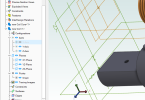
I have a coil (helix) and a core. I want to constrain the coil around the core in an assembly. Normally I would expect to do this by referencing the longitudinal axes (in this case X for both) and a coaxial constraint and it would be done. However in the Assembly space, the X axis for the coil doesn't seem to be available to reference. It appears in the part sketch but doesn't carry through to the Assembly. When I invoke the Assembly Constraints dialog, I can select various parts of the two components and am presented with some constraint options, but not coaxial, and none of the presented options work. The X axis for the core is there, but not for the coil, I am unable to use those.
I feel I'm missing something fundamental but not obvious to me. I've already spent a few hours on this and searched the forum without finding a solution. Rather than going on at length and possibly confusing the description even more, I have attached the file in the hope that an experienced user will be able to see where I'm going wrong and set me straight.
Thanks,
Tom

