What's new

assembly level part fitting/manipulation

danwrnr11

Member
I am in the process of doing a drawing for a mailbox post and am having trouble orientating the 2 components "vertical & horizontal posts" in the assembly drawing. I have incorporated a "crosslap" joint where the poles cross but am having trouble rotating the individual posts in the assembly level drawing to get the joints to fit together, any help appreciated
 

Attachments

  • mail box post horizontal.AD_PRT
    305.5 KB · Views: 1
  • mail box post horizontal1.AD_PRT
    305.5 KB · Views: 1
  • mailbox post_vertical.AD_PRT
    307.5 KB · Views: 3
  • mailbox post_vertical1.AD_PRT
    307.5 KB · Views: 1

HaroldL

Alibre Super User
If you have an assembly started could you upload that as a Package file? (File>Package>Create)
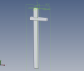
You've uploaded two each of the vertical and horizontal posts so I my guess is that you want the assembly to look something like this:
1677709427554.png

So the first thing is to right click on the vertical post and select Show Reference Geometry from the pop up menu. Then apply a constraint between the parts' default planes and the assembly workspace planes. Then apply constraints between the horizontal post and the vertical post using the faces of the cutout notches.

Here's a v26 assembly for reference.
 

Attachments

  • mail post assy.AD_PKG
    66.7 KB · Views: 2
Top