What's new

Basic questions with placement and moving parts

JST

Alibre Super User
OK... Background.....
I have used 2D autocad for something like 30 years..... This probably fouls me up here....... But I am used to being able to put a block (part) in an assembly precisely, and being able to rotate it to a specific orientation and position relative to other features, etc.

I am still using AD 12.1, but can upgrade to 14 (does it still run on XP?) and no I am not upgrading it until I get a specific project done..... no time for those problems added to all else. I have had AD for some time, but have not got serious about it again until recently.

Yes I am the dummy who thought I'd pick up where I left off and knock this project out.

before you ask, I did go through the tutorials again, found they match neither the actual program (symbols, names, views, capabilities and definitely results often different from what is described * ), nor what I want to do. They are OK as a demo.

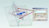
I have what I thought was an understanding of the constraints..... but for instance.... I have a bunch of TO247 cased IGBTs oriented parallel to a heatsink plane, with 0.25mm offset up for the insulator to be added later. But half of them are 180 deg from the orientation they should be in.

I used the "mate with offset" to get them in the right plane, and the heatsink base is anchored, as the "foundation" for all else. There are a scad of parts made, but still to be added to the unit, PWBS, case, parts to mate up with holes in the case, etc.

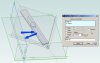
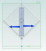
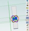
I can use an "approximate" method to turn these IGBTs around, but then they are not actually 180 deg, just something that looks close (toggle triad rotate). When I want them oriented, and try to constrain them with an edge parallel to the edge of the heatsink, AD complains they are "overconstrained". But they slide around in their plane fine now, and will rotate OK, so there is obviously a list of constraints that are "open", at least x, y position and rotation.

I have a feeling I am just missing something basic, because I don't seem to be able to get to where I have these located or rotated correctly.

If they had holes, they'd be easy, at least for position, line them up. But they clamp down, and have no holes. I need to put them in a position relative to other features, and I just don't "get it" for that, nor do I "get it" for precise rotation 180 deg. I don't think the tutorials I went through really covered this.

Sorry for being a dummy, I HAVE searched......

As this isn't really a problem with THIS assembly, I don't think there is a reason to try to attach it for specific debugging.

Thanks in advance for tolerating dummies......

*
I had the same issue of the pocket turning out as a "mesa" that another poster I found when searching did.... I never resolved that, but it was just the tutorial, and I ignored it then.
 

Jim C

Senior Member
Just a thought, can you insert a plane perpendicular to your working base and then align say the top of the part to the plane, either with or without an offset? You can define planes precisely. Alternately an axis will also work.

I still have autocad 12 but now am using Alibre 2012 all the time. It takes a bit of rethinking but now I just autocad to pick views to import to Alibre.

Jim c
 

JST

Alibre Super User
Maybe you can, but I have no clue what you mean....!

Insert plane? Eh?

I think I have them turned correctly, I thought I needed a constraint, but actually what I needed was "precise placement". Part, axis, angle.

OK, wrong initial approach.

Now..... exact location.......

Do I have to somehow do a sketch (no idea how to link that in) and use that for position? The precise placement seems to want me to tell it exactly how much I want to move it...... but I want a definite position.

Am I seeing that backwards also?
 

JST

Alibre Super User
My clumsy workaround on this positioning issue is to align with some other feature, like a corner, etc, and then specify precise position from that.

Probably helps if it is a feature that won't move later relative to desired position, but that seems not always to be possible.

I would be pretty sure that this isn't the right way.... its so clumsy, and besides, the way to do these same things in sketch mode is far nicer, so the programmers clearly knew better.
 

RCH_Projects

Alibre Super User
My first suggestion and perhaps most useful.

Right click the part you want to place and select "Show Reference Geometry".

Do the same for the part you want to align with.

This gives you something to start with.

Helpful?
 

RCH_Projects

Alibre Super User
"Precise placement" is not the tool you need to learn at all (others may disagree). I never use it for anything and only would for an object to be placed in some undefinable space.

Use the "Constraint" tool.


I am using menu references since they change less between versions.
They exist as a quick ribbon select.
 

Attachments

  • Constraint.jpg
    Constraint.jpg
    63.4 KB · Views: 3

RCH_Projects

Alibre Super User
If this doesn't get you going, fake up an assembly with a few part examples you have trouble with as a "STEP" file and post it here. Then we can be more helpful.
 

JST

Alibre Super User
Do you have that in english? I believe I am "AD SL"...... like ESL but different......

The precise position worked for a while, but now I have mated parts that I can move around, but which are described as error overconstrained if I try to align some things collinear, although it worked great on 3 of them. It seems to have stopped working when I anchored the three parts that I managed to get into the right place.


I see the references to constraints, but there is no part to constrain their location yet, that part is to be added later on top of them. Plus their constraint is a square peg in round hole type of constraint, and I don't have the round hole anyway.
 

JST

Alibre Super User
Actually, it screamed, held its breath and turned blue, with all kinds of pop-up errors claiming that the "mate" conflicted with moving the part in the plane, but the precise positioning did do the moves to correct location. I anchored those parts so I don't have to do this over.........

Maybe it isn't the right tool, but it was the only one I saw that COULD do the job, there isn't any other reference.

I don't understand the geometry viewer deal, I'll try that at some point.
 

RCH_Projects

Alibre Super User
When you anchor a part it invalidates all the constraints that you created to place it. Anchor is a 100% never move again in any manner.

Normally you anchor "1" part. Usually the first part in the assembly that all the other parts constrain too.

We'll get you there.
 

rollin45

Senior Member
Generally when I am inserting part into an assembly I follow this procedure, though of course it varies as to what is needed. First after inserting the first part and getting it placed , I will anchor it. The next part is then brought in, if it needs spinning or rolling etc. in order to get it heading in the right direction with respect to the first part, I will use precise placement and use the axis, then rotation ... sometimes this takes more than just one translation. You can also use edges of the part to use as an axis of rotation.

Then, I am usually not near enough to the first part to easily put part two into place, so I use the triad tool,.. by clicking on a face or an edge, you can restrict movement of the part to one of three axis' by clicking on one of the three corresponding axis arrows, by clicking on an axis arrow, you are enabled to drag your part along the chosen axis, simply left click and hold the part while dragging it,, sometimes this also takes a few moves to get close .

Then I will generally go to the contraint tool, by aligning two sides, two axis' or faces, edges, etc. etc. one can postion the two parts exactly, this too may take a couple of constraints to nail the position exactly. Once this position is "right", I will anchor the second part. Occasionally when aligning two parts the moveable part will do a 180, if this happens I yell and kick something, and then re-do the steps to get the parts close, and then I get them closer before applying the restraint. This usually works, once in while I have had to add another restraint to keep this from occuring. Often when anchoring the second part , one or more of the previous constraints, ..align, mate etc. will go kerflooey, in that they will appear in italics in the design explorer. I simply right click and delete the contraints that show bad. If the two parts are anchored, they will stay in position.

As was mentioned , by causing reference geometry to be shown, you can also use these planes and axis', for both placement and constraints. Once you have things in place you can "turn off" reference geometry for each part as it's placed, things can get pretty cluttered otherwise.

hth

rollin'
 

RCH_Projects

Alibre Super User
Unless you have a LOT of time on your hands you should move parts with the mouse.

If you select the part and keep left mouse down you can drag the part near its position - if you hold down the <shift> key while moving, the part rotates at the arrow point in the direction you move the mouse; it's a valuable skill.

The Left and right mouse button can be used to rotate the entire asembly.

The mouse scroll zooms the assembly in or out.
 

JST

Alibre Super User
rollin......

That sounds like reality based advice, thank you...... What you say corresponds exactly to what I see. And to the hassles that seem to pop up.

I have to put it aside for now to run errands...... I actually got all 6 of the parts put in the right place, and it took only a minute to pop in the insulators, but those do not require placement other than a "mate" on the surface at zero offset, and a rough position" within the lines". They won't be put in any better in production.

It's bad when your "quick project" starts to involve re-learning, and some first-time learning as well.... it doesn't go quite so fast then..... animals and children are well advised to stay away......... ;)
 

rollin45

Senior Member
If later on you have to move one of the anchored parts, you can simply remove the anchor over in the design explorer, move it to its new home and re-anchor. You can turn on/off the reference geometry of a part in the design explorer by right clicking the part, drop down menu gives this as an option (as I recall and I know all about relearning... :mrgreen: )

Glad that made sense, and hope it helps, lots of folks here are much better at doing some of this stuff than I and are always willing to help.

rollin'
 

RCH_Projects

Alibre Super User
rollin45 said:
...
Occasionally when aligning two parts the moveable part will do a 180 ...
rollin'

Of course we all have our own techniques so variations apply. I don't ever try to use "Quick constraint mode" so my suggestion regards the "Insert asssembly constraint"

There are posts related to "surface norms" but my bottom line:


The Blue Arrow "surface norms" will display when selected.
When they are in the same direction there is no flipping using "ALIGN".
When in opposite directions there is no flipping using "MATE".

If in doubt about the result, clicking the "PREVIEW" option on and off will display/undo the results without actually changing anything.

After turning the part upside down, the (new default) and correct constraint is "MATE" to prevent flipping.


If you turn on "Preview" and click through constraint options you learn what does and does not happen pretty fast.
If you select part faces or edges then only the "Preview" will let you see if the part flips.
So I usually just keep "Preview" on all the time.

This is the part finally mated:


But it takes "three" constraint directions to "fully constrain" and keep a part from moving.
Without two more constraints it will still move in/out, up/down, spin top to bottom; but will not move left or right.
Using an axis constraint stops movement in 2 directions so "two" constraints do the same as "three".

Or of course you could anchor it and (suppress) or delete the constraints that go bad.

The big trouble with anchoring and then deleting bad constraints a lot is that as a project grows - the chance of an unrelated error on a needed constraint is possible.
 

Attachments

  • Align.jpg
    Align.jpg
    120.5 KB · Views: 12
  • Mate.jpg
    Mate.jpg
    102.4 KB · Views: 6
  • Mated.jpg
    Mated.jpg
    35.8 KB · Views: 7

RCH_Projects

Alibre Super User
OK - "that" triad.

I've never noticed or used it, but a good addition to general placement.
Even better when used with the shift key.
With keyboard <shift> key held down, temporary movement becomes rotational and releasing <shift> restores current triad direction!

Excellent! Always plenty to learn - thanks!
 

Attachments

  • Triad.jpg
    Triad.jpg
    63.4 KB · Views: 6

jimbees

Senior Member
Anchoring a part when you have it constrained to another fixed point will give you overconstrained problems. It is good practice to anchor one part only then constrain everything with 3 constraints per part to that part or to convenient planes. Anchoring the first part should be done before any constraints are applied to prevent unexpected movement. Constraining a second part to a position then anchoring it and removing the constraints is not good practice and risks leaving in a constraint which can give you problems later. Like others here, I very rarely use precise placement as constraints can get you where you need to be.

It is hard to get out of Autocad thinking, where the start point of any line is intrinsically defined in 3 planes. AD just puts parts randomly in an assembly, until you constrain them in 3 planes or a 2 planes and an axis, they are just floating in space, free to be moved about by seemingly unrelated actions. This implies that a fully constrained assembly should have roughly 3 times as many constraints as parts, many less experienced people are not expecting this. I find it better to constrain to a fixed (anchored) part or a plane as much as possible, if you daisy chain constraints and have to remove one constraint if you change a part etc. it can take quite a while to track down where the repair needs to be made.

Jim
 

rollin45

Senior Member
Perhaps my assemblies have not been complex enough to run into problems, however, I've never run into difficulty by anchoring successive parts once they were located properly. I have however, run into difficulties when constantly adding contraints to various parts as I continued the assembly as inevitably I get over contrained errors. Then trying to track these down and eliminate the offender takes more time and effort than it was worth. As I say , perhaps my assemblies weren't of a complex enough nature to discover the inherent pitfall, but color me unconvinced at this point. 8)
rollin'
 
Top