What's new

Basic things that still need to be done

9 years ago.... https://www.alibreforum.com/forum/index.php?threads/most-useful-feature-in-v12.9982/#post-58624

It really is about time that Extrude or Sweep to another Parts geometry worked, in a way that has any use whatsoever!
Miles -- Whereas Interdesign References can be (and are) quite powerful, they need to be included within a Part's definition to make a Part truly a (if you will) stand-alone component in your Design toolkit. Thus, should you wish ti use an external Parts Geometry to provide a Feature Control for an Extrude or Sweep, you need to construct said Geometry within the target Part, then Hide it within said Part and move such Geometry to an Invisible Layer in the Drawing used to define it. Yes, this is a PITA, but it does work!

Now, should you wish ti ask for things such as: improved Constraints, a richer set of Curve Entities, or other things that improve basic Part or Assembly creation, I will be happy to join in the chorus.
 

MilesH

Alibre Super User
Lew, I'm all for improved constraints etc. etc. but Extrude To Geometry in the context of an Assembly is a pretty basic feature for 'top down' modelling and it's already been, embarrassingly, half implemented!
 
Lew, I'm all for improved constraints etc. etc. but Extrude To Geometry in the context of an Assembly is a pretty basic feature for 'top down' modelling and it's already been embarrassingly half implemented!
Ah, but if you created the Geometry you need, then Projrect Variable make "transferring" it fairly simple within the context of InterDesign Relations. Properly applied, a change in one creates a change in the other.
 

MilesH

Alibre Super User
Alibre needs to implement the basic top down modelling features that every other MCAD had in the last century. Using ghost geometry with global variables is far too complicated, time consuming and inflexible. Top down modelling is most often used for initial designs, one offs, modelling of existing objects etc. The last thing you need is to get bogged down with the interdesign process itself....
 

MilesH

Alibre Super User
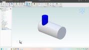
The red Part is what you get if you choose Extrude To Geometry and reference the green Part.... The red Part is "adaptive geometry", just a bit limited by its implementation........


InterPart Extrude to Geometry.jpg
 
Last edited:

MilesH

Alibre Super User
Thanks Lew but I'm afraid I can't open it (still on 2017.1).

I'm really not short of ways to do things.

The 'To Geometry' option is needed between Parts for the same reason that it's needed within a Part. Sure, one can usually project and trim in both cases.
 
Thanks Lew but I'm afraid I can't open it (still on 2017.1).
In essence, I merely created 2 (identical) Configurations of the "Stacks" that could each, separately, be "Extruded to" the "Tank Shell" as InterDesign Relations. Simple, quick, and easy.
 

MilesH

Alibre Super User
Ref: https://www.alibreforum.com/forum/index.php?threads/tube-notching.14708/

Improvements to Top Down modelling. With specific reference to the creation of tubular structures.

- Access to the Reference Geometry of all Parts whilst creating or editing a Part within Assembly.

- Access to Assembly Reference Geometry whilst creating or editing a Part within Assembly.
- Extrude/Sweep To Geometry of another Part whilst creating or editing a Part within Assembly.
[Ref. https://receptive.io/app/#/case/41869]

- Bi-Directional "To Geometry" & "To Next" option for Extrude and Sweep
[Ref. https://receptive.io/app/#/case/41846]
 
Last edited:

HaroldL

Alibre Super User
Lew, I downloaded and opened your package file. Upon opening it I created a 3d Section view and saw this:
Extrude To Geometry.png
So how is this supposed to work? :confused: As Miles points out, in the context of top down assembly modeling, Extrude To Geometry does not create a part that conforms to the geometry surface it is being extruded to.
 
Lew, I downloaded and opened your package file. Upon opening it I created a 3d Section view and saw this:
View attachment 26215
So how is this supposed to work? :confused: As Miles points out, in the context of top down assembly modeling, Extrude To Geometry does not create a part that conforms to the geometry surface it is being extruded to.
Harold -- Each of the "Stacks" (a different Configuration) Extrudes to the Tank from a diofferent "elevation" above the "Tank," and each is "lengthed" accordingly.
 

HaroldL

Alibre Super User
I've not tried this scenario before in previous versions of AD but if it did work as you intended I wonder if something got broke with the last update.

The "intent" may be to extend to the tank but the "result" doesn't show that. In the image I posted only the RH stack is "To" the tank, the LH stack has gone through the surface and is in the tank. Something doesn't seem right. If I "Edit Here" stack 1, it is set to use Config Stack 01 and when I edit the Extrude (Stack Basis) the Extrude Type is To Geometry with the tank selected. When I close the Extrude dialog both stacks update to the length of stack 1 and stack 2 stops short of the tank surface. It seems that stack 2 is adopting the length defined by stack 1, and visa versa, even though the extrude types are set To Geometry in each config.

I think there may be a problem with the configurations not "locking" the Extrude Type even though all locks are selected. I edited stack 1 and changed the Extrude Type to Blind and set its distance to just touch the tank. When I closed the extrude dialog and went back to the main assembly both stacks had updated to the new type and length and stack 2 has pulled away from the tank. I don't think that should have happened if the Extrude Type is locked when All Locks are selected. IF the extrude type is set to Blind then each config will maintain its own, and different, Depth value.
 

MilesH

Alibre Super User
I may be missing the whole point but Extrude to Next seems to do what you want. Doesn't it?

View attachment 26217
Yikes! That is between 2 different Parts in an Assembly? What version are you using? To Next doesn't even half work, like To Geometry does, for me (v. 2017.1.2). Apply is greyed out if there is only geometry from another Part in the path.
 

BrianE.Evans

Senior Member
I am having a similar difficulty on a sheet metal part this morning When I try to do an extrude cut to next The button greys out and will not let me complete the operation . AD thickness and distance buttons work just fine.
 

albie0803

Alibre Super User
OK, so I definitely was missing the point. I didn't realise you were trying to do that with an assembly and you're right, it doessn't work.
 

HaroldL

Alibre Super User
I am having a similar difficulty on a sheet metal part this morning When I try to do an extrude cut to next The button greys out and will not let me complete the operation . AD thickness and distance buttons work just fine.
:confused:
I was just able to perform a cut using the Part Modeling Extrude Cut with To Next in a sheet metal part. I created the sketch on a plane that was offset from the surface and To Next cut through just the one sheet metal panel. Another panel that was offset from the first was left untouched, as would be expected.
I take that you are using the Part Modeling Extrude Cut since the Extrude Cut in Sheet Metal does not have a To Next option, only To Depth, Through All and Mid Plane.
 

Ex Machina

Senior Member
OK, I'm not saying it's efficient. I'm just saying that it can be done.

To geometry between parts.jpg
 

Attachments

  • To geometry between parts.AD_PKG
    42.9 KB · Views: 3
Top