What's new

Bend angles on 2D Drawings On project to flat pattern

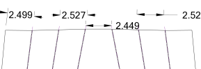
Hi Everyone, first of all I'm very new to sheet metal and 2d drawings but I'm trying to send some 2D drawings and DXF's of sheet metal parts out to get laser cut and bent. Just wondering what would be the best method to detail the drawing as simple and clear as possible. the brake operator sent me an example of what he would like to see which is a flat pattern with the center of bend lines displayed, and then the bend angles displayed along those bend lines. He also has the distance between the bend line centers. I can't seem to figure out how to display the appropriate angles he is looking for in the project to flat pattern. Any help would be greatly appreciated.
 

HaroldL

Alibre Super User
Once you have the Flat Pattern view in the drawing, LM click on it and select Add Centers from the Manage View pop up tool bar.
You will have to add dimensions and bend directions manually between the center lines and the the blank end.

Just checking, but I suppose you already have the correct Bend Allowance or K-factor in the part based on the dies your brake operator will be using.

And are you still providing dimensioned views of the formed part? All my experience has been working off the dimensioned views, no dims between bend lines on the flat pattern view. But I was using a brake press with a programmable back gauge that accounted for the Bend Allowances


1673401823577.png
 
Last edited:
Great example, yes this is exactly what I'm after. I had everything except the Up or Down 90. I guess you just have to type that in? Also one thing I noticed is if 2 bend centerlines come in to the edge of pattern at opposite or "mirrored" angles, I haven't found a way to accurately dimension between those two lines at the edge of the blank.

Yes I did make sure I had the correct K factor for his equipment.

Interesting, so any part I send him that requires bending, he asked for me to send something identical to your example, a STEP file and DXF for the laser. I assume he is using the STEP for the information you would have got from the other drawing views you mentioned? They do have a top notch brake press as well that is programable but it sounds like he maybe using a different approach than you were. This machine they have is pretty new to them as well so I think they are still learning how to get the most out of it.

Thank you for the reply.
 

HaroldL

Alibre Super User
Great example, yes this is exactly what I'm after. I had everything except the Up or Down 90. I guess you just have to type that in? Also one thing I noticed is if 2 bend centerlines come in to the edge of pattern at opposite or "mirrored" angles, I haven't found a way to accurately dimension between those two lines at the edge of the blank.
Not sure what you mean without a screen shot of the issue but, I think you may need to activate Sketch in View then place a point near where each of the centerlines and edge of the part intersect. Then add a Coincident constraint between the points and the edge of the part then between the points and the CL's. Then you can dimension to the point and the edge of the part or between the two points.

Yes I did make sure I had the correct K factor for his equipment.

Interesting, so any part I send him that requires bending, he asked for me to send something identical to your example, a STEP file and DXF for the laser. I assume he is using the STEP for the information you would have got from the other drawing views you mentioned? They do have a top notch brake press as well that is programable but it sounds like he maybe using a different approach than you were. This machine they have is pretty new to them as well so I think they are still learning how to get the most out of it.

Thank you for the reply.
It's likely that he is importing the STEP file into a CAD program so he can generate some internal drawings for dimensioning all the views. That's what we did when working on customer parts. And he definitely needs the DXF for the laser.

It would be interesting to know what make of brake press that is being used. When I learned to operate a press brake the company had a hodge-podge of old mechanical brakes. I learned on an old Chicago with all manual controls and adjustments. When I transferred into Design the company started replacing all the old mechanical brakes with Cincinnati CNC press brakes in all departments and when I retired they were replacing them with Trumpf True Bend machines, which are highly programmable.
 
Yes once I realized the issue, I figured I could insert a point at the two intersections however it doesn't seem to allow me to do that... Perhaps I am doing something wrong? I can insert a point at other intersections just not at the centerline intersections.

He is using a Tumpf True Bend as well.

See attached example. the issue is the distance between the two centerlines in the middle of the part where the two angles are mirrored or opposed. I am also questioning the other dimensions now too because they also have a slight angle to them as this is a lofted part.
 

Attachments

  • Dimensioning issue.PNG
    Dimensioning issue.PNG
    36.7 KB · Views: 5
Further to my last reply, I just tried inserting points at those locations again, and now I realize when I try to drop a point there, it creates a node in the middle of nowhere. See attached image where the nodes or "X" 's were placed when I try to drop them on the centerline and part edge intersection.
 

Attachments

  • Node placement issue.PNG
    Node placement issue.PNG
    19.1 KB · Views: 9

jroy

Member
Further to my last reply, I just tried inserting points at those locations again, and now I realize when I try to drop a point there, it creates a node in the middle of nowhere. See attached image where the nodes or "X" 's were placed when I try to drop them on the centerline and part edge intersection.
Hi Jacques,
have you tried disabling the snap to grid option on the sketch?
Have a nice day,
 
Ah yes, that's probably it. I thought I disabled that everywhere but I will check and try that when I get home tonight. Great point, Thanks.
 
Thank You jroy, that's exactly what I overlooked I just tried it now. I'm wondering if there is a way to terminate the center lines at the part edge? It would be a real time saver if I could do that and then dimension between two center line ends.
 

HaroldL

Alibre Super User
Thank You jroy, that's exactly what I overlooked I just tried it now. I'm wondering if there is a way to terminate the center lines at the part edge? It would be a real time saver if I could do that and then dimension between two center line ends.
I never use Grid or Snap to Grid and so leave both turned OFF.

You can change the centerline extension to zero in the File Properties. Just be aware that it will affect ALL centerlines on the drawing.

extension line.jpg

Without centerlines displayed, you can zoom way in on the bend region and mouse over the lines at the edge of the part and pick a point to dimension to.
dim to points.gif

And one other option is to select the centerline and, while it is highlighted, select its end node and drag it to the edge of the part. Tedious if you have a lot of centerlines to edit.

drag cl ext.gif
 
Top