What's new

Can Alibre flatten this surface?

bengal

Member
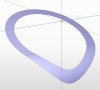
So glad Alibre is back, haven't messed with it since about 2008 when I modeled a pressure vessel on the demo. Curious if it can flatten this surface somehow, see attached image. This is a surface of a nozzle reinforcement pad which goes on a tank head in the knuckle area which makes it tricky.

Couldn't flatten it as a sheet metal part in Bricscad V16 due to the curves being non-planar and the surface tools are limited so that's a dead end. Could try the demo again but thought maybe some Alibre gurus can give some insight on this, thanks!
 

Attachments

  • surface-repad.JPG
    surface-repad.JPG
    32.4 KB · Views: 38

bigseb

Alibre Super User
Can you upload a model? It'll help others help you.

FWIW the best software for flattening surfaces (in my opinion) is Creo Parametric.
 

bigseb

Alibre Super User
Ok... problems... it appears to be a 3D dwg file that I cannot covert to anything useful. The layout file looks like a corrupted non-manifold solid and the surface file is very coarse, almost low-poly. Where did you get them? Can you get a better version, or create your own? Maybe someone else here open and convert it...
 

HaroldL

Alibre Super User
As bigseb indicated, your file is corrupt and won't open in Alibre.
However, this was no problem to create in Alibre; I took a guess at dimensions.
repad sheet metal  example.png
 

Attachments

  • repad sheet metal example.AD_SMP
    328.5 KB · Views: 15

bengal

Member
Ok... problems... it appears to be a 3D dwg file that I cannot covert to anything useful. The layout file looks like a corrupted non-manifold solid and the surface file is very coarse, almost low-poly. Where did you get them? Can you get a better version, or create your own? Maybe someone else here open and convert it...

It's probably corrupt because I tried too many boolean operations over and over. Really this kind of thing is beyond the depth of the program I'm using but as shown else where this post Alibre apparently can do it. For those up to the challenge I've attached the actual 2D layouts if you want to try it from scratch. For the record I'm an "old school" 2D user trying to adapt to this 3D stuff, but I do love it!
 

Attachments

  • manway repad 2D layout.zip
    35.5 KB · Views: 8

HaroldL

Alibre Super User
:oops:Well your latest files sheds a lot of light on the situation. I didn't catch that this was on a tank head, that means the sheet metal has no flat surface and from the image it appeared that it did. Alibre can only form flat sheet metal parts with straight bends. The part can be approximated in Alibre but it would not fit surface-to-surface on the tank head.
There is the possibility that something could be done using the Lofted flange option but that, I think, will be an experiment for another day.
Here is my attempt so far...close but no cigar.TankHeadWmt.png
 

Attachments

  • TankHeadWmt.AD_PKG
    167.2 KB · Views: 9

JST

Alibre Super User
A curved surface SHOULD be. I see the problem with a compound curve.

Can that be done on a simple curve as a workaround by having a 0.001 wide flat at each end, and a bend radius to suit?

I am not sure the problem of a compound curve even "has a solution" when considered as a "bend".

There are ways of developing it by mechanical drafting means. That suggests that there might be a similar means to get there in Alibre, but.....
 

HaroldL

Alibre Super User
Because of the compound curvature of this part it is best formed by a stamping process. Using Alibre or any of the other straight brake forming design software like SolidWorks, Solid Edge, NX, etc. will only approximate the part. I don't think that would be acceptable in this case.
 

Nick952

Senior Member
I've had some sheet metal forms to do recently , that although fairly simple, had compound curves.
My workaround was to convert the model to a surface and then export the surface as a STL file to a Mesh Unfolding program (I use a program coveniently called "Mesh Unfolder 3").
I've already put in a suggestion that Alibre incorporates a Mesh Unfolding ability (Although it does not show up on the "Dashboard" in the Feature Suggest, for some reason)

Nick.
 
Last edited:
Because of the compound curvature of this part it is best formed by a stamping process. Using Alibre or any of the other straight brake forming design software like SolidWorks, Solid Edge, NX, etc. will only approximate the part. I don't think that would be acceptable in this case.
This is one of the reasons I dislike the term Sheetmetal to describe the module. I "cut my teeth" (as it were) on matched die-forming toolsets instead of sheetmetal formers.
 

bengal

Member
Because of the compound curvature of this part it is best formed by a stamping process. Using Alibre or any of the other straight brake forming design software like SolidWorks, Solid Edge, NX, etc. will only approximate the part. I don't think that would be acceptable in this case.

An approximation would be good enough, typical pressure vessel tolerances are +/- 1/8", so you get as close as you can then reach for the sledge hammer for "fine tuning". I ended up playing around with Rhino for the better part of the day and finally got something "close" and transferred it to a dwg file. See attached for the proposed layout, if we use it I'll chime in on how it goes.
 

Attachments

  • manway repad layout.pdf
    49 KB · Views: 16
Top