What's new

Can't rotate cam lobe on z axis

Art K

Member
Hi,
I have drawn a cam lobe and want to rotate it in 90 degree increments around the Z axis. I am making a camshaft and thought it would be easier to draw it up once and copy into the right plane location then extrude boss. Then go on to the next one. I have attached the file rather than a screen shot. I have been going to surfacing, move/rotate. When I am in the move surfaces dialog box I can set move type to precise rotate and the angle to 90, and the axis edge to Z but cant select any surface.
Art
 

Attachments

  • intake cam lobe arts design Offy.AD_PRT
    277.5 KB · Views: 21
Art -- A Part is "fixed" within it's Design Space. An Assembly allows a Part to be controlled by an Equation Editor Variable (or Suppressing the appropriate Constraint allow you to "manually royate" it). Take a kook at the attached Package for an example.
 

Attachments

  • Cam Rotatr Assy LM20190125.AD_PKG
    54 KB · Views: 9

HaroldL

Alibre Super User
Art,
Another option is to create a Boolean Unite. Then just constrain the lobes 90 degrees apart.

CamShaft_BooleanExample.png
 

Attachments

  • CamShaft_BooleanExample.AD_PKG
    107.8 KB · Views: 5

Art K

Member
Thanks for your help, but I wasn't able to open either of the files due to the version I'm using is so ancient. I then discovered I had a day left on maintenance and made the misguided attempt to download the recent one and couldn't enter the key. then reinstalled the version that was uninstalled, messy.
Art
 
Art -- I can arrange to do a GoToMeeting with you to show you different approaches. [I am in American Pacific Coast Time otherwise known as GMT-8.] You can contact me at tangent@olympus.net with a date and time should you be interested. -- Lew
 

NateLiquidGravity

Alibre Super User
Hi Art,

Lew and HaroldL are on the right path but there is one more thing to save some time. The Circular Part/Subassembly Pattern to pattern as many at whatever spacing and incremental rotation (twist Angle) you like. See the attached image. This can be done while making the boolean or in an assembly.

Layers and twist angle options are not currently but should really be added to the part feature pattern tool as well.
 

Attachments

  • twist_angle.png
    twist_angle.png
    33.7 KB · Views: 18

albie0803

Alibre Super User
Thanks for your help, but I wasn't able to open either of the files due to the version I'm using is so ancient. I then discovered I had a day left on maintenance and made the misguided attempt to download the recent one and couldn't enter the key. then reinstalled the version that was uninstalled, messy.
Art
Art, talk to support about getting your key. The fact that you were entitled to the upgrade on the day you tried should be enough ( I would expect) to make the effort worthwhile.
 

HaroldL

Alibre Super User
Hi Art,

Lew and HaroldL are on the right path but there is one more thing to save some time. The Circular Part/Subassembly Pattern to pattern as many at whatever spacing and incremental rotation (twist Angle) you like. See the attached image. This can be done while making the boolean or in an assembly.

Layers and twist angle options are not currently but should really be added to the part feature pattern tool as well.
Good call, Nate. Not sure why I didn't remember that, I just used it on my RSJ steam tractor model to pattern the steering chain.:oops: 
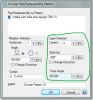
And you're right, it should be in the part feature pattern tool.
 

Art K

Member
Thanks,
I went went to support which has the instant messaging tool. I was informed of their hours and asked for an email so they could reach me. To be honest I didn't realize I had any remaining maintenance. The version I have after yesterdays mess isn't the same one I was using and I cant seem to be able to get the toolbar on the r/h side as I had been using. Right now I'm going to try what Nate said, if I can find it. Otherwise I'm on vacation and have a long drive ahead tomorrow, and won't be doing much till after Monday.
 

Art K

Member
I didn't get that figured out but went about it by copying the view in NESW views. I got the new version sorted out and have maintenance now, and did find the "Circular Part/Subassembly Pattern" function but couldn't figure it out. Lew I think I would like help on this as I realize for everything I do know in this software there are 10 I don't know. I may change my cam design in the future so the knowledge to do this in an easier manner would be time well spent. I have heard of Boolian but know little more than the title.
I do have another question though. The camshaft has lubrication holes, if I do them from the center axis out, using the extrude cut function, will that give me problems later? Or do I need to add a plane and do the same thing cept the starting point of the hole on the outside and going in to the center?
Art
 

Attachments

  • intake cam Offy.AD_PRT
    986 KB · Views: 6
Top